A drilling method preventing secondary pollution for reconnaissance of a polluted site

A secondary pollution and site technology, applied in the direction of sampling, measuring devices, instruments, etc., can solve the problems of misjudgment of pollution range, secondary pollution, pollutants brought into the deep, etc., and achieve simple device, easy operation, and suitable for promotion Effect

Inactive Publication Date: 2016-04-27
SHANGHAI GEOTECHN INVESTIGATIONS & DESIGN INST
View PDF7 Cites 6 Cited by
  • Summary
  • Abstract
  • Description
  • Claims
  • Application Information

AI Technical Summary

Problems solved by technology

[0003] The site investigation needs to collect the soil and groundwater of the site for detection, and to measure the concentration of pollutants. Generally, if soil at different depths needs to be collected, drilling and sampling are required. To collect groundwater samples, groundwater monitoring wells need to be built. Traditional drilling and sampling may The surface or shallow pollutants will be brought into the deep, and the pollution isolation is not achieved. During the site investigation process, large-scale drilling and sampling are required. If effective measures are not taken for segmental isolation, the pollutants in the site will spread. produce secondary pollution
[0004] Pollution isolation in the investigation process is of great significance. It not only avoids the diffusion of site pollutants caused by the investigation process, but also can truly reflect the actual pollution situation and scope at different depths of the site, and avoids the contamination range caused by cross-contamination during the investigation process. However, at the current stage, pollution isolation cannot be achieved in the process of domestic site survey work. Effective isolation is conducive to ensuring the accuracy of the investigation and the protection of the groundwater and soil environment, so there is an urgent need for a method to prevent secondary pollution. Contaminated Contaminated Site Drilling Methods

Method used


Image

  • A drilling method preventing secondary pollution for reconnaissance of a polluted site
  • A drilling method preventing secondary pollution for reconnaissance of a polluted site
  • A drilling method preventing secondary pollution for reconnaissance of a polluted site

Examples


Embodiment

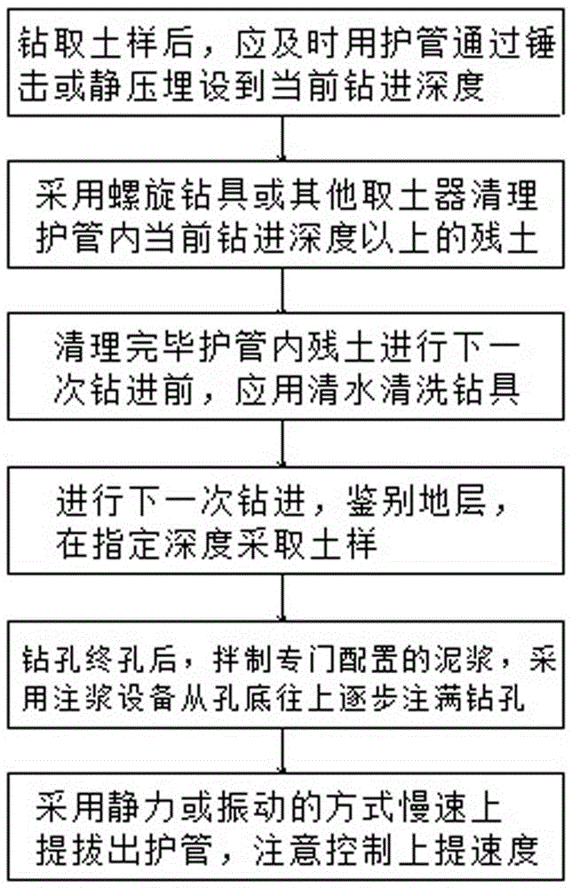
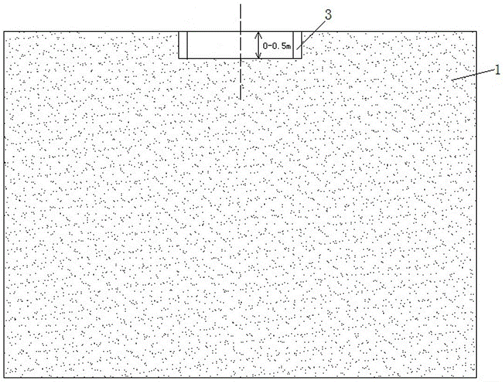
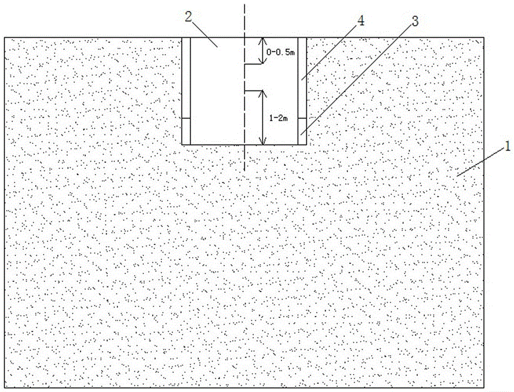
[0027] Embodiment: In this embodiment, the drilling method for preventing secondary pollution in polluted site investigation will be described in conjunction with a simulation example. The simulation example is as follows: According to data analysis, there may be organic pollution in a certain contaminated site 1, and it is necessary to collect soil samples in the three specified depth ranges of 0-0.5m, 1-2m and 3-4m in the contaminated site 1 as soil samples. The monitoring factors for soil samples are: pH, TPH, VOC and SVOC. Since disturbances should be avoided during VOC sampling, undisturbed soil fetchers and drilling rigs should be used for on-site sampling.

[0028] The drilling method is as follows figure 1 The implementation of the steps shown, steps 1-4 in the figure, is a process of repeated cycle implementation (unless the drilling has reached the final depth—that is, the depth of the final hole), and each step has the following instructions:

[0029] 1) Collect t...


PUM


Abstract

The invention relates to the field of environmental geotechnics and particularly relates to a drilling method preventing secondary pollution for reconnaissance of a polluted site. The method is characterized in that after the polluted site is drilled to a prescribed depth and soil layer identification or sampling is finished, a protective tube the diameter of which is larger than the diameter of a drilling hole and the length of which allows the tube to reach the present drilling depth is implanted into the drilling hole, thus separating underground water and hole circumferential soil of the drilling hole from the hole opening to the present depth. The method is advantageous in that accuracy of reconnaissance for the site is ensured, cross contamination of water and soil of different depths in reconnaissance processes is effectively prevented, pollution dispersal caused in reconnaissance processes is effectively controlled, the polluted range of the site can be reflected veritably, and the method is convenient in construction, simple in device, convenient to operate and suitable for popularization.

Description

technical field [0001] The invention relates to the field of environmental geotechnical engineering, in particular to a drilling method for preventing secondary pollution in surveying polluted sites. Background technique [0002] In recent years, the relocation of industrial enterprises and the redevelopment of legacy sites have become increasingly urgent. In order to avoid harm to human health and the ecological environment after changing the land use mode of industrial sites, it is necessary to conduct necessary investigations, assessments, and even restoration of the sites. [0003] The site investigation needs to collect the soil and groundwater of the site for detection, and to measure the concentration of pollutants. Generally, if soil at different depths needs to be collected, drilling and sampling are required. To collect groundwater samples, groundwater monitoring wells need to be built. Traditional drilling and sampling may The surface or shallow pollutants will be...

Claims


Application Information

Patent Timeline
Patent Type & Authority Applications(China)
IPC IPC(8): G01N1/08G01N1/10
CPCG01N1/08G01N1/10G01N2001/1031
Inventor 夏群许丽萍王蓉叶萌冯凯
Owner SHANGHAI GEOTECHN INVESTIGATIONS & DESIGN INST
Why Eureka
Try Eureka