
Electromagnet structure

A technology of electromagnet and blocking structure, which is applied in the direction of electromagnet with armature, electromagnet, circuit, etc. It can solve the problems of increasing power consumption, increasing the coil, and difficulty in meeting the demand, and achieve the effect of avoiding bias

Active Publication Date: 2016-04-27
DELIXI ELECTRIC
View PDF8 Cites 5 Cited by
  • Summary
  • Abstract
  • Description
  • Claims
  • Application Information

AI Technical Summary

Problems solved by technology

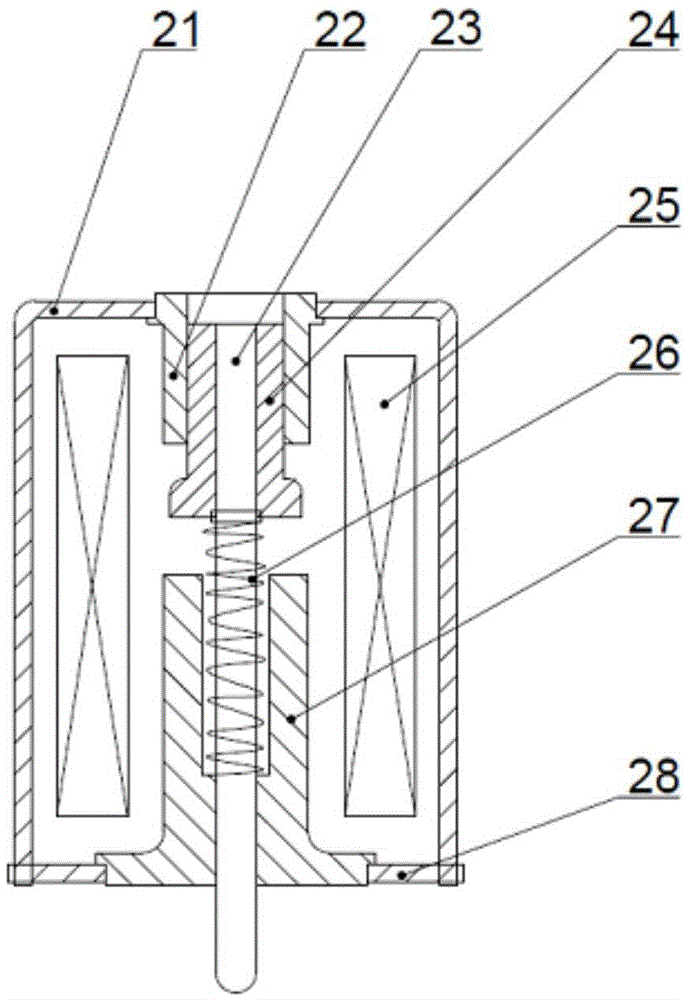
[0003] However, with this electromagnet structure in the prior art, when the coil 25 is energized, the force with which the moving magnetic pole 24 drives the push rod 23 to stretch out is relatively small, and it is difficult to meet the demand in some occasions that require a large driving force.
In order to increase the force that the moving magnetic pole 24 drives the push rod 23 to stretch out, people generally adopt two methods, the first is to increase the current inside the coil 25, and the second is to increase the coil; however, the first method will increase Power consumption, and lead to serious heating, the second method will lead to excessive coil volume, which is not conducive to the miniaturization of the product

Method used


Image

  • Electromagnet structure
  • Electromagnet structure
  • Electromagnet structure

Examples


Embodiment 1

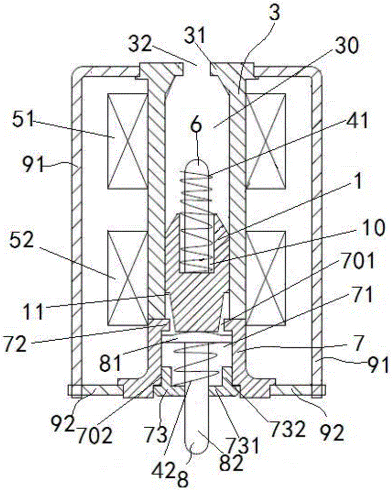
[0050] This embodiment provides an electromagnet structure, which does not include a push rod structure. For specific structures, refer to image 3 shown, including:

[0051] Magnetic pole 1, capable of moving under the action of a magnetic field;

[0052] The mounting part 3 is installed in cooperation with the magnetic pole 1, used to guide the movement of the magnetic pole 1, and has a first blocking structure 31 opposite to the magnetic pole 1;

[0053] The first elastic member 41 is installed between the magnetic pole 1 and the first blocking structure 31;

[0054] The first coil 51 is arranged around the mounting part 3 and is close to the first blocking structure 31 for generating a magnetic field when electrified to attract the magnetic pole 1 close to the first blocking structure 31 to compress the first blocking structure 31 An elastic member 41 stores energy;

[0055] The second coil 52 is arranged around the mounting part 3 and away from the first blocking struc...

Embodiment 2

[0069] This implementation provides an electromagnet structure, such as image 3 As shown, while including the structure described in Embodiment 1, a mandrel structure is also included.

[0070] Wherein the ejector rod structure includes: a base 7, which is arranged opposite to the end of the mounting part 3 away from the first blocking structure 31, has an installation space 71, communicates with the installation space 71, and allows the insertion of the magnetic pole 1 a first opening 701, and a second opening 702 opposite to the first opening 701;

[0071] The push rod 8 has a blocking portion 81 located inside the installation space 71 , and a main body portion 82 connected to the blocking portion 81 and capable of protruding from the second opening 702 ;

[0072] The second blocking structure 72 is disposed on the inner wall of the first opening 701 and used to block each other with the blocking portion 81 ;

[0073] The third blocking structure 73 is disposed on the in...


PUM


Abstract

The invention provides an electromagnet structure. The electromagnet structure comprises a magnetic pole, a mounting member used for mounting the magnetic pole and guiding the movement of the magnetic pole, and a first coil and a second coil arranged around the mounting member, a first blocking structure is arranged on the mounting member, and a first elastic member is arranged between the magnetic pole and the first blocking structure; when being energized, the first coil generates a magnetic field to attract the magnetic pole to a position close to the first blocking structure, and at this time, the first elastic member is compressed to store energy; when the first coil de-energized, the second coil is energized, the second coil generates a magnetic force to attract the magnetic pole to move towards one side away from the first blocking structure, at this time, the first elastic member releases the energy to propel the magnetic pole to accelerate, so that when the magnetic pole arrives at the position of the second coil, the magnetic pole can obtain a larger speed, and thus being capable of driving the action of a mandril in a larger force. Compared with the prior art, the magnetic pole drives the movement of the mandril in the larger force without increasing the current or the coil, and demands under specific occasions can be satisfied.

Description

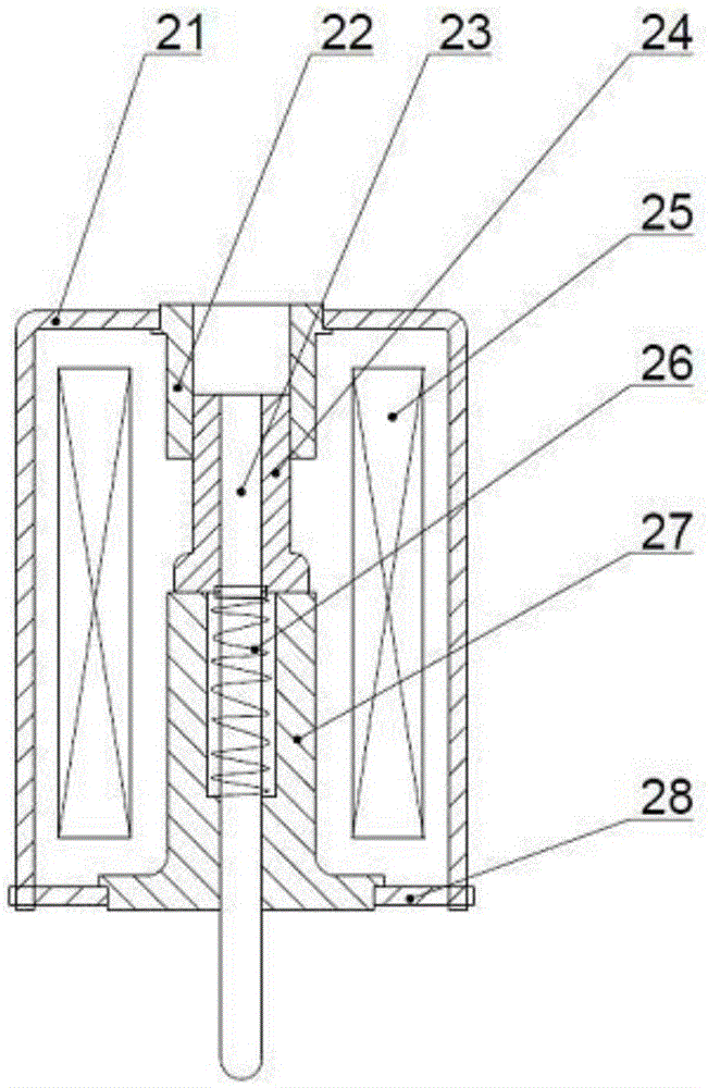
technical field [0001] The invention relates to an electromagnet structure and belongs to the technical field of electrical control and protection devices. Background technique [0002] Electromagnet structures are often used in electrical control devices to provide power for control actions. The electromagnet structure in the prior art is as figure 1 As shown, the moving magnetic pole 24 and the static magnetic pole 27 which are arranged relatively are included, wherein the static magnetic pole 27 is fixedly arranged, and the moving magnetic pole 24 can move back and forth relative to the static magnetic pole 27. There is a through hole for driving the push rod 23 to pass through, and a return spring 26 is sleeved on the outer wall of the drive push rod 23, and one end of the return spring 26 contacts with the moving magnetic pole 24, and the other end contacts with the static magnetic pole 27; A coil 25 is also provided on the circumferential outer side of the static mag...

Claims


Application Information

Patent Timeline
Patent Type & Authority Applications(China)
IPC IPC(8): H01F7/08H01F7/123H01F7/16
CPCH01F7/081H01F7/123H01F7/16H01F2007/1692
Inventor 朱华轩吉涛张俊
Owner DELIXI ELECTRIC
Learn More