Vehicle power unit

A power unit and vehicle technology, which is applied to vehicle parts, vehicle gearboxes, bicycles, etc., can solve the problems of power unit expansion, achieve the effect of improving the degree of freedom, realizing miniaturization, and avoiding expansion

Active Publication Date: 2016-04-27
HONDA MOTOR CO LTD
View PDF8 Cites 0 Cited by
  • Summary
  • Abstract
  • Description
  • Claims
  • Application Information

AI Technical Summary

Problems solved by technology

However, when arranging a plurality of rotational speed sensors in the power unit, it is necessary to secure a space for arranging these rotational speed sensors, which may lead to enlargement of the power unit, and it is also necessary to consider interference with peripheral parts.

Method used


Image

  • Vehicle power unit
  • Vehicle power unit
  • Vehicle power unit

Examples


no. 1 approach

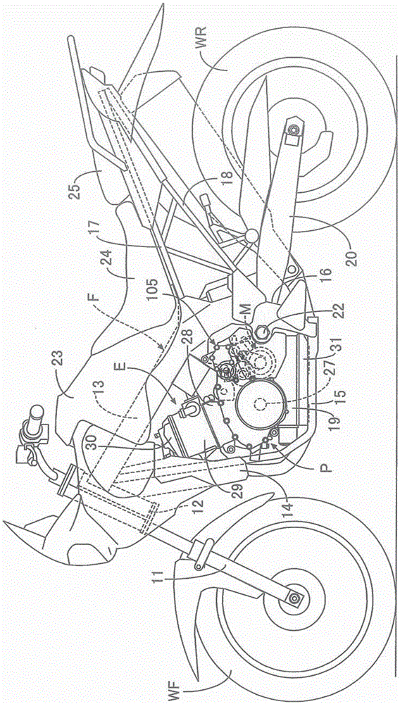
[0079] First, in figure 1 Among them, the frame F of a motorcycle that is a straddle-type vehicle includes: a head pipe 12 that supports a front fork 11 that pivotally supports a front wheel WF so as to be steerable; A pair of left and right main frames 13; a pair of left and right descending frames 14 extending backward and downward with a sharper inclination than the above-mentioned main frame 13; a lower frame 15 extending backward from the lower ends of the two descending frames 14; The rear end of the main frame 13 extends downward and a pair of left and right central frames 16 connected to the rear ends of the two lower frames 15; a seat rail 17 ; and a pair of left and right rear subframes 18 connecting the lower portion of the center frame 16 and the rear portion of the seat rail 17 .

[0080] In the area surrounded by the main frame 13, the down frame 14, the lower frame 15, and the center frame 16, a two-cylinder internal combustion engine E and a transmission M (re...


PUM


Abstract

A vehicle power unit for which a transmission, which is equipped with a gear transmission mechanism having a gear train of multiple gear ranges that can be established alternately and a gear selection mechanism that enables the gear train to operate so as to establish the multiple gear ranges alternately, is housed in a transmission case. Multiple rotational frequency sensors which separately detect the rotational frequency of multiple rotation members forming a portion of the transmission are attached to the transmission gear case. The multiple rotational frequency sensors (S1, S2, S3) are arranged in a dispersed manner in a projection view on a plane orthogonal to the axial center line (C1) of the crankshaft (27) so as to sandwich therebetween multiple shaft members (81, 82, 83, 84) possessed by the gear selection mechanism (51). Thus, it is possible to provide the multiple rotational frequency sensors on the case without increasing the size of the power unit.

Description

technical field [0001] The present invention relates to a power unit for a vehicle, which houses a transmission equipped with a gear transmission mechanism and a gear selection mechanism in a transmission case mounted on a vehicle frame. The main shaft can input power from the crankshaft of the internal combustion engine, and the intermediate shaft is arranged parallel to the main shaft at a position offset in the vertical direction relative to the main shaft, and simultaneously with the main shaft. The driving wheels are interlocked and connected, and the gear selection mechanism is configured to have a plurality of shaft members, and the plurality of shaft members are connected to the main shaft and the intermediate shaft on the side opposite to the crankshaft with respect to the virtual plane. arranged in parallel, the imaginary plane passes through the central axis of the main shaft and the central axis of the intermediate shaft, and the gear selection mechanism can work i...

Claims


Application Information

Patent Timeline
Patent Type & Authority Applications(China)
IPC IPC(8): F16H63/18B60K17/06F16H59/42F16H61/00
CPCB60K17/06F16H59/42F16H61/00F16H63/18B60K17/08B60Y2200/12F16H61/688F16H3/006F16H59/38F16H57/02F16H57/025B62M11/04F16H3/091F16H63/08
Inventor 菅野刚林典生三堀敏正
Owner HONDA MOTOR CO LTD
Why Eureka
Try Eureka