Robot calibration system and method based on incomplete end coordinate information
A coordinate information, robot technology, applied in the field of robot calibration system, can solve the problems of complicated operation steps, low positioning accuracy and high equipment cost
- Summary
- Abstract
- Description
- Claims
- Application Information
AI Technical Summary
Problems solved by technology
Method used
Image
Examples
Embodiment 1
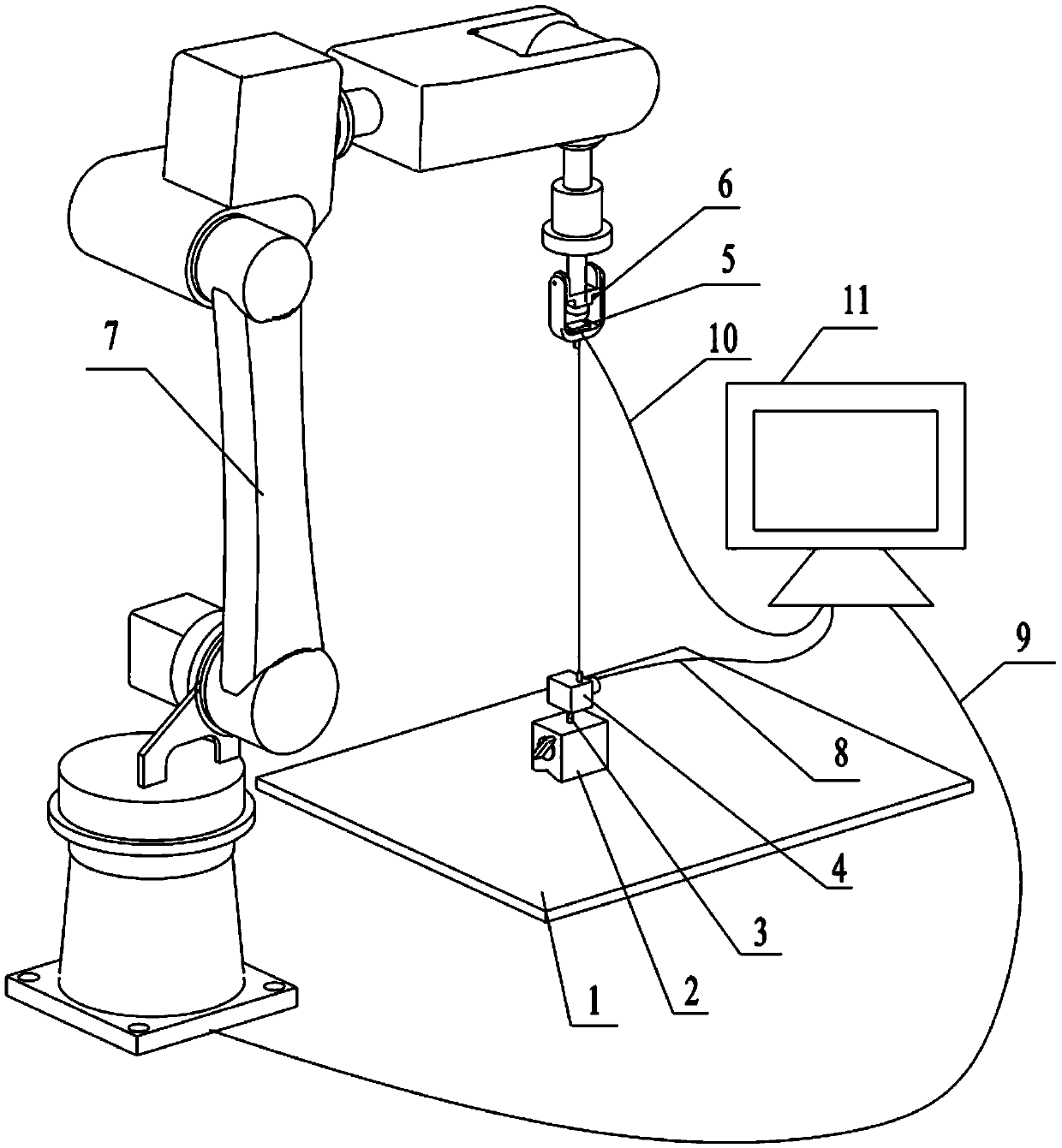
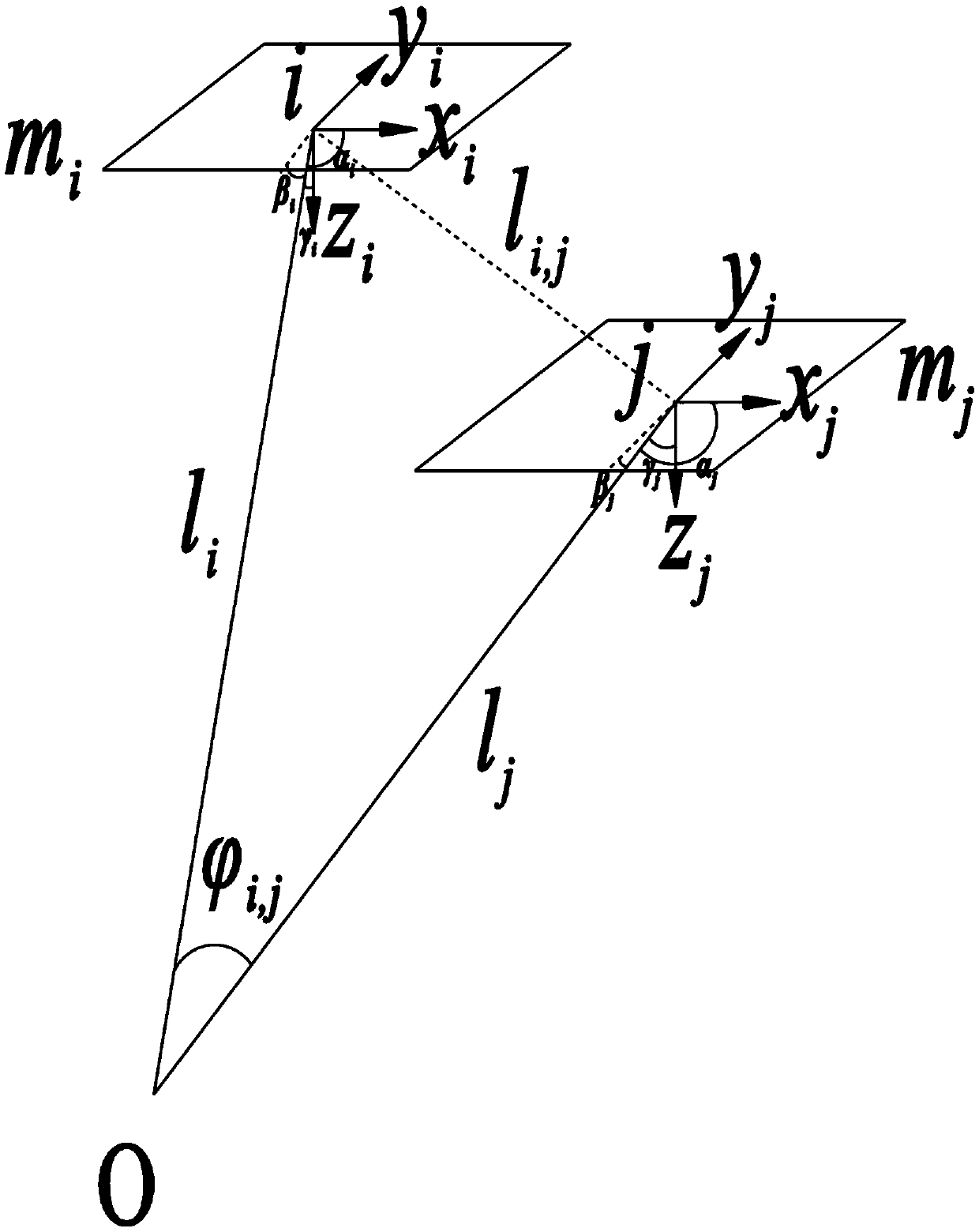
[0047] Embodiment 1: as Figure 1-2 As shown, a robot calibration system based on incomplete coordinate information at the end, including a fixed platform 1, a magnetic base 2, a connecting rod 3, a wire sensor 4, an inclination sensor 5, a universal joint 6, a robot 7, and a wire sensor cable 8 , robot cable 9, inclination sensor cable 10, computer 11;
[0048] The magnetic base 2 is mounted on the fixed platform 1 by magnetic force, the magnetic base 2 and the wire sensor 4 are connected together through the connecting rod 3, the end of the wire of the wire sensor 4 is installed on the universal joint 6, and on the universal joint 6 Attached with an inclination sensor 5, the inclination sensor 5 moves with the universal joint 6, and the universal joint 6 is installed on the robot 7; the pull wire sensor 4 and the inclination sensor 5 are respectively connected to the computer 11 through the pull wire sensor cable 8 and the inclination sensor cable 10. , the robot 7 is conne...
Embodiment 2
[0080] Embodiment 2: as Figure 1-2 As shown, a robot calibration system based on incomplete coordinate information at the end, including a fixed platform 1, a magnetic base 2, a connecting rod 3, a wire sensor 4, an inclination sensor 5, a universal joint 6, a robot 7, and a wire sensor cable 8 , robot cable 9, inclination sensor cable 10, computer 11;
[0081] The magnetic base 2 is mounted on the fixed platform 1 by magnetic force, the magnetic base 2 and the wire sensor 4 are connected together through the connecting rod 3, the end of the wire of the wire sensor 4 is installed on the universal joint 6, and on the universal joint 6 Attached with an inclination sensor 5, the inclination sensor 5 moves with the universal joint 6, and the universal joint 6 is installed on the robot 7; the pull wire sensor 4 and the inclination sensor 5 are respectively connected to the computer 11 through the pull wire sensor cable 8 and the inclination sensor cable 10. , the robot 7 is conne...
Embodiment 3
[0082] Embodiment 3: as Figure 1-2 As shown, a robot calibration method based on non-complete coordinate information of the end, the specific steps of the method are as follows:
[0083] Step1, paste the inclination sensor 5 on the universal joint 6, and install the universal joint 6 on the end of the robot 7;
[0084] Step2, install the pull wire sensor 4 on the magnetic watch base 2 through the connecting rod 3, and fix the magnetic watch base 2, and connect the pull wire of the pull wire sensor 4 to the end of the universal joint 6;
[0085] Step3, power on, turn on the inclination sensor 5, the cable sensor 4, and the robot 7, and move the robot 7 to the initial pose and satisfy the initialization count variable v=0;
[0086] Step4, judging whether to complete the data acquisition operation;
[0087] If the data collection has been completed, go to Step7; if not, go to Step4;
[0088] Step5. The counting variable is incremented by 1: v=v+1;
[0089] Step6, collect the...
PUM
 Abstract
Description
Claims
Application Information
 - R&D
- Intellectual Property
- Life Sciences
- Materials
- Tech Scout
- Unparalleled Data Quality
- Higher Quality Content
- 60% Fewer Hallucinations
Browse by: Latest US Patents, China's latest patents, Technical Efficacy Thesaurus, Application Domain, Technology Topic, Popular Technical Reports.
© 2025 PatSnap. All rights reserved.Legal|Privacy policy|Modern Slavery Act Transparency Statement|Sitemap|About US| Contact US: help@patsnap.com


