Miniature mechanical sliding rail type controllable flapping rotor craft

A micro-mechanical, slide rail-type technology, applied in the field of aircraft, can solve problems such as flutter, achieve the effect of stable flight, overcome the horizontal shaking of the body, and compact overall structure

Inactive Publication Date: 2016-05-04
BEIHANG UNIV
View PDF7 Cites 14 Cited by
  • Summary
  • Abstract
  • Description
  • Claims
  • Application Information

AI Technical Summary

Problems solved by technology

[0005] Aiming at the above-mentioned miniaturization and structural simplification requirements of the miniature flapping rotor aircraft, and in order to solve the flutter

Method used


Image

  • Miniature mechanical sliding rail type controllable flapping rotor craft
  • Miniature mechanical sliding rail type controllable flapping rotor craft
  • Miniature mechanical sliding rail type controllable flapping rotor craft

Examples


Embodiment Construction

[0034] The present invention will be further described in detail with reference to the accompanying drawings and embodiments.

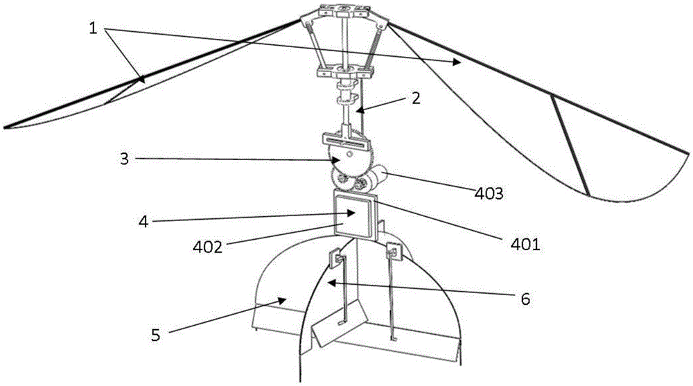
[0035] A kind of micro-mechanical slide rail type flapping rotor aircraft of the present invention, as figure 1 As shown, it includes a wing 1, a fuselage 2, a transmission mechanism 3, a power unit 4, a forward flight control device 5, and a steering control device 6.

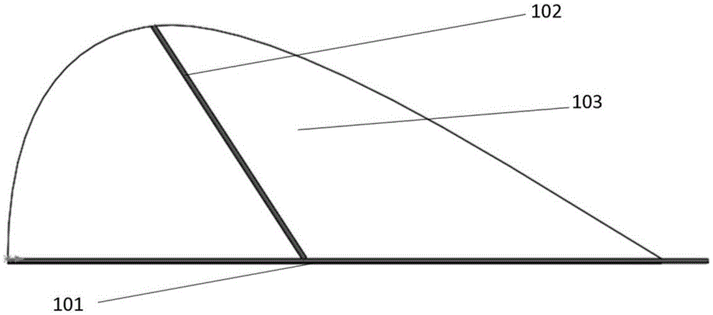
[0036] Wing 1 as figure 2 As shown, it includes a wing main spar 101 , a wing auxiliary spar 102 , and a film 103 . The root of the wing main beam 101 is fixed to the wing mounting frame 307 of the transmission mechanism 3; the wing auxiliary beam 102 is glued to the wing main beam 101 at a certain angle; and above the wing spar 102.

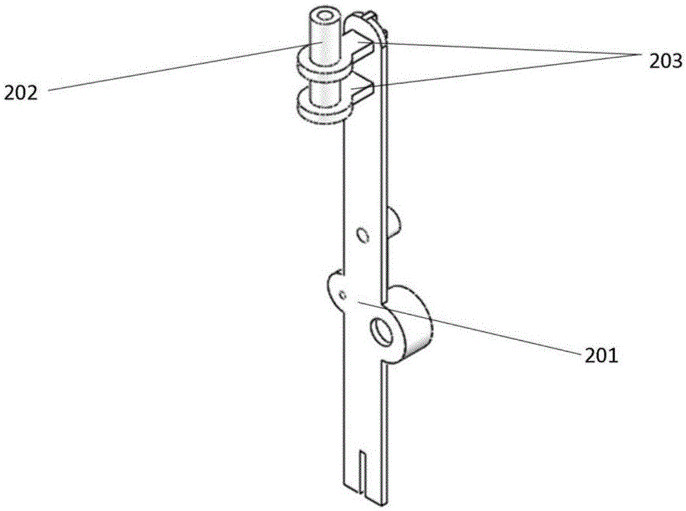
[0037] fuselage 2 as image 3 As shown, it includes a plate structure 201 capable of fixing motors and gears, a sleeve 202 , and two sleeve supports 203 . The sleeve 202 is fixedly connected to the plate structure 201 through two support members 2...


PUM


Abstract

The invention discloses a miniature mechanical sliding rail type controllable flapping rotor craft. According to the principle of rotors, the rotors are driven by a motor, the rotors flap by the adoption of a mechanical manner of a sliding rail, then the rotors rotate, lifting force is generated by flaps and rotation of the rotors, and therefore the craft can fly. The craft is remarkably improved for solving the problems existing in existing flapping rotors, the vertical lifting function, the hovering function, the steering control function and the natural forward flying function of the flapping rotors are achieved, the problem that the flapping rotors vibrate in the horizontal direction is effectively solved, the structure compactness is greatly improved, and the weight losing effect is remarkable.

Description

technical field [0001] The invention relates to the field of aircraft, and more specifically, the invention relates to a micro-mechanical slide rail type controllable flapping rotor aircraft. Background technique [0002] Micro air vehicles are currently a research hotspot in the field of international aviation. Research at home and abroad generally divides micro air vehicles into three types according to the flight mode: micro fixed-wing aircraft, micro rotor aircraft, and micro flapping-wing aircraft. Compared with fixed-wing aircraft, the biggest advantage of micro-rotor aircraft is that it can take off and land vertically and hover, which is more suitable for use in more complex environments. However, the existing rotorcraft either adopts the form of multi-rotor active rotation; or adopts a single rotor active rotation and cooperates with a tail rotor to offset the torque generated by the rotor to the body, resulting in complex structure and large mass. The micro flappi...

Claims


Application Information

Patent Timeline
IPC IPC(8): B64C33/00B64C33/02B64C13/34B64D27/24
CPCB64C33/00B64C13/34B64C33/02B64D27/24
Inventor 李道春向锦武安琦甄冲
Owner BEIHANG UNIV
Why Eureka
Try Eureka