Compactor for making fiber module

A technology of fiber modules and compactors, applied in the field of compactors, can solve problems such as poor work efficiency, many processing procedures, and poor flexibility, and achieve the effects of high work efficiency, reasonable structural design, and improved work efficiency

Inactive Publication Date: 2016-05-04
JIANGSU SOUTH ENERGY SAVING TECHNOLOGY CO LTD
View PDF4 Cites 1 Cited by
  • Summary
  • Abstract
  • Description
  • Claims
  • Application Information

AI Technical Summary

Problems solved by technology

[0002] In order to improve the plasticity of steel and change the crystalline structure in the structure, it is often necessary to place the billet in a heating furnace for heating treatment, and the roof design of the heating furnace has a significant impact on the furnace temperature and work efficiency. The temperature inside the furnace needs to compress the fiber modules in the furnace roof. Due to the simple structure and poor flexibility of the traditional fiber module compressors, it is troublesome to pack them with plastic film after the compression is completed, and manual handling is required; further, When packaging, the opening of the plastic film needs the cooperation of multiple people to open it, and put the compressed fiber module into it. There are many processing steps and poor work efficiency. Therefore, it is urgent to develop a reasonable structure setting, good flexibility and one-time completion. A compacting machine for making compressed and packaged fiber modules, no technical solutions identical or similar to those of the present invention have been found after searching

Method used


Image

  • Compactor for making fiber module

Examples


Embodiment Construction

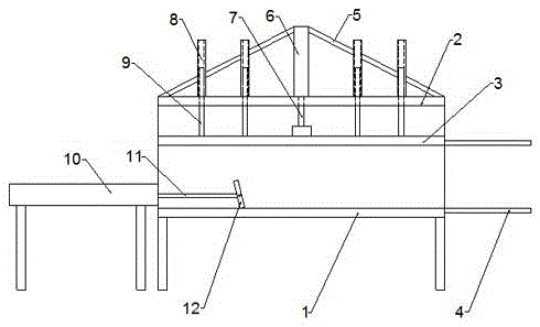
[0014] Such as figure 1 As shown, the present invention discloses a compacting machine for fabricating fiber modules, which includes a compacting machine body, a pressing plate 3 arranged on the compacting machine body and a driving mechanism.

[0015] The compactor body includes a workbench 1 and a mounting plate 2 fixed on the top of the workbench 1. Several round pipes 8 are vertically fixed on the mounting plate 2; 1 parallel, several guide rods 9 are vertically fixed at the same vertical line position on the upper end surface of the pressure plate 3 and the circular pipe 8, the guide rods 9 slide and fit with the circular pipe 8, and the pressure plate 3 and the workbench 1 are far away from the same side where the cylinder 10 is pushed A set of boards 4 are arranged on the sides.

[0016] The drive mechanism includes a compression cylinder 6 vertically fixed on the mounting plate 2 and a push cylinder 10 arranged parallel to the workbench 1; wherein the cylinder piston ...


PUM


Abstract

The invention relates to a compactor for making a fiber module. The compactor comprises a compactor body, and a pressing plate and a driving mechanism which are arranged on the compactor body; the compactor body comprises a worktable, and a mounting plate fixed above the worktable, and the pressing plate is arranged between the worktable and the mounting plate and parallel to the worktable; the driving mechanism comprises a compacting cylinder vertically fixed on the mounting plate and a pushing cylinder arranged in parallel to the worktable; a cylinder piston rod A of the compacting cylinder is connected with an upper end face of the pressing plate; the pushing cylinder is arranged at a side edge of an upper end face of the worktable, and an end portion of a cylinder piston rod B of the pushing cylinder is hinged to a push plate. The compactor for making the fiber module has the advantages that the compactor for making the fiber module is mainly applied to process the fiber module needed for use in a furnace roof, a fiber blanket is compacted by the compacting cylinder, and then the compacted fiber module is pushed into a plastic thin film sleeve by the pushing cylinder, and the whole operation process is simple, convenient, and high in working efficiency.

Description

technical field [0001] The invention relates to a compacting machine, in particular to a compacting machine for fabricating fiber modules. Background technique [0002] In order to improve the plasticity of steel and change the crystalline structure in the structure, it is often necessary to place the billet in a heating furnace for heating treatment, and the roof design of the heating furnace has a significant impact on the furnace temperature and work efficiency. The temperature inside the furnace needs to compress the fiber modules in the furnace roof. Due to the simple structure and poor flexibility of the traditional fiber module compressors, it is troublesome to pack them with plastic film after the compression is completed, and manual handling is required; further, When packaging, the opening of the plastic film needs the cooperation of multiple people to open it, and put the compressed fiber module into it. There are many processing steps and poor work efficiency. Th...

Claims


Application Information

Patent Timeline
IPC IPC(8): B65B63/02B65B35/20
CPCB65B63/02B65B35/20
Inventor 张超尹常青魏海峰
Owner JIANGSU SOUTH ENERGY SAVING TECHNOLOGY CO LTD
Why Eureka
Try Eureka