Quick draining pavement structure for urban low-lying roads

A pavement structure, low-lying technology, applied in the direction of roads, roads, pavement details, etc., can solve the problems of high cost, high water storage tank materials, high technology, limited number of water storage tanks, etc., and achieve the effect of reducing rainwater runoff

Active Publication Date: 2016-05-04
SOUTHEAST UNIV
View PDF5 Cites 5 Cited by
  • Summary
  • Abstract
  • Description
  • Claims
  • Application Information

AI Technical Summary

Problems solved by technology

Although this method is relatively advanced, it cannot solve the problem of water accumulation in low-lying areas. When the water passes through the drainage surface layer, the water will run off to the low-lying areas according to the slope of the road. Only part of the rainwater that can be collected by the drainage pipes will be collected. During severe rainstorms, the runoff of rainwater on roads with higher elevations will not be completely collected by the drainage pipes. Eventually, the water storage tanks on roads with higher elevations will not be filled, while the road water storage tanks in low-lying areas will be filled. Phenomenon of flooding
At the same time, this kind of pavement structure is relatively expensive for the material and process of the water storage tank, and the cost is relatively expensive, and the number of water storage tanks is limited. When the amount of rainwater exceeds a certain limit, the drainage will fail
At the same time, the rainwater accumulated and used by this method belongs to artificial circulation, which does not meet the current concept of sponge city. How to realize rapid drainage, especially solve the accumulation of water in low-lying road sections, and at the same time realize the natural circulation of road surface drainage

Method used


Image

  • Quick draining pavement structure for urban low-lying roads
  • Quick draining pavement structure for urban low-lying roads
  • Quick draining pavement structure for urban low-lying roads

Examples


Embodiment Construction

[0021] The present invention will be further described below in conjunction with the accompanying drawings.

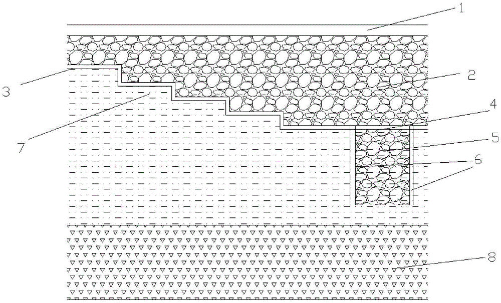
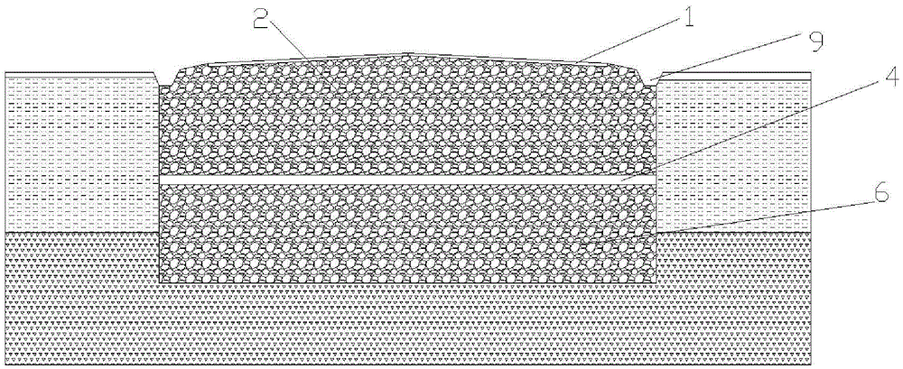
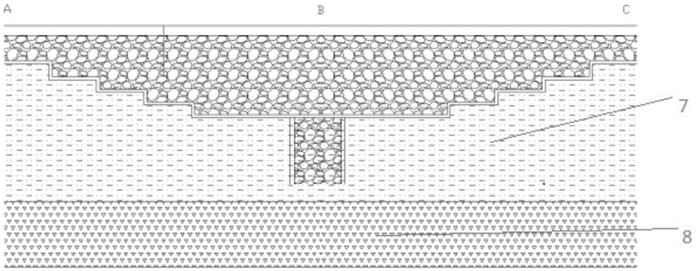
[0022] Such as figure 1 , figure 2 Shown is a rapid drainage pavement structure for urban low-lying roads, including a motor vehicle lane surface layer 1, a flexible base layer 2 is arranged under the motor vehicle lane surface layer 1, and a The drainage ditch 9, the drainage ditch 9 is within the scope of the flexible base layer 2, and the rainwater in the drainage ditch 9 enters the flexible base layer 2 through infiltration.

[0023] Below the flexible base 2 is the soil foundation 7, and a water-repellent layer 3 is set between the flexible base 2 and the soil foundation 7. The water-resistant layer 3 includes an asphalt slurry seal layer and a reflection fabric layer, and the reflection fabric layers are laid on On the soil base 7, the asphalt slurry seal layer is laid on the reflection fabric layer. The side of the flexible base 2 facing the soil foundation ...


PUM


Abstract

The invention discloses a quick draining pavement structure for urban low-lying roads. The structure comprises a pavement motor way surface layer, a flexible base is arranged below the pavement motor way surface layer, soil base is arranged below the flexible base, a water-resisting layer is arranged between the flexible base and the soil base, and one flexible base side facing the soil base is design as a stepped structure. The stepped surface at a road section low-lying part is high, and the stepped surface at a road section high convex part is low, if the height of some stepped surface is lower than those of two adjacent stepped surfaces, or some stepped surface only has one adjacent stepped surface and the stepped surface is lower than the adjacent stepped surface, a gravel drainage channel can be disposed below the stepped surface, and a filter layer is arranged between the flexible base and the gravel drainage channel. The quick draining pavement structure provided by the invention can solve the technical problems of impeded pavement drainage and easy waterlogging in existing urban road low-lying areas, and is especially suitable for paving of urban roads with large elevation difference between adjacent road sections.

Description

technical field [0001] The invention relates to road paving technology, in particular to a rapid drainage pavement structure for urban low-lying roads. Background technique [0002] Drainage of urban roads is crucial to driving safety. At present, the urban road drainage technology has been relatively perfect, and the main pavement drainage systems are mainly divided into three categories, namely, pavement surface drainage, median strip drainage and internal drainage of pavement structure. However, in many large and medium-sized cities, there are still severe rainstorms, and the road area is seriously flooded. What is more serious is that there has been no good solution for the drainage of low-lying roads. Surface runoff and sewer pipes converge on road sections with low elevations. When the height difference is large, there may even be water spray from sewer pipes in low-lying areas. These have seriously affected the safety and convenience of urban road traffic and brought...

Claims


Application Information

Patent Timeline
Patent Type & Authority Applications(China)
IPC IPC(8): E01C11/22
CPCE01C11/225
Inventor 黄晓明丁珣昊刘修宇曹青青巩金芝王飔奇闫天昊彭龙
Owner SOUTHEAST UNIV
Why Eureka
Try Eureka