Damping ditch with pressure relief device and shockproof plates and construction method for damping ditch

A pressure relief device and anti-vibration plate technology, which is applied in protection devices, infrastructure engineering, construction, etc., can solve the problems of no internal support system, inconspicuous effect of shock-absorbing trenches, difficult vibration reduction and isolation, etc., to achieve enhanced shock absorption and shock-isolation effect, improve shock-absorbing and shock-isolation effect, improve shock-absorbing and shock-isolation effect

Active Publication Date: 2016-05-04
浙江易通特种基础工程股份有限公司
View PDF8 Cites 2 Cited by
  • Summary
  • Abstract
  • Description
  • Claims
  • Application Information

AI Technical Summary

Problems solved by technology

[0004] The damping ditch of the above-mentioned prior art has the following disadvantages: one, water is easy to accumulate in the ditch, and the longitudinal wave generated by the vibration can be transmitted through the liquid, so naturally the effect of shock absorption or shock isolation cannot be achieved after the ditch accumulates water; two, The above-mentioned shock-absorbing ditch has no internal support system, and if it is dug too deep, it may cause collapse. However, if the effect of shock-absorbing or shock-isolation is to be achieved, the depth of the ditch is often required to be more than twice the depth of the object to be protected. The depth of the ditch is limited, which objectively fails to meet the requirements of shock absorption and isolation; 3. The internal structure of the above-mentioned shock absorption ditch is too simple, only a groove is hollowed out, and the air or sand filling in the groove is used for shock absorption, while the longitudinal wave energy of vibration Through gas, liquid and solid transmission, so the damping ditch effect of the prior art is not obvious, and the damping effect is very unsatisfactory; There is also groundwater under the underground pipeline, and the longitudinal wave of vibration will propagate outward along the groundwater system with water as the medium. Since the position of the propagation path is very low, this part of the vibration is difficult to reduce and isolate

Method used


Image

  • Damping ditch with pressure relief device and shockproof plates and construction method for damping ditch
  • Damping ditch with pressure relief device and shockproof plates and construction method for damping ditch

Examples


Embodiment Construction

[0026] The present invention will be further described below in conjunction with the accompanying drawings and specific embodiments.

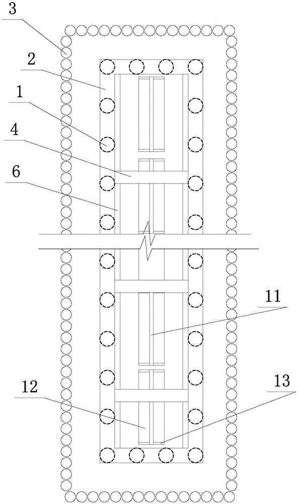
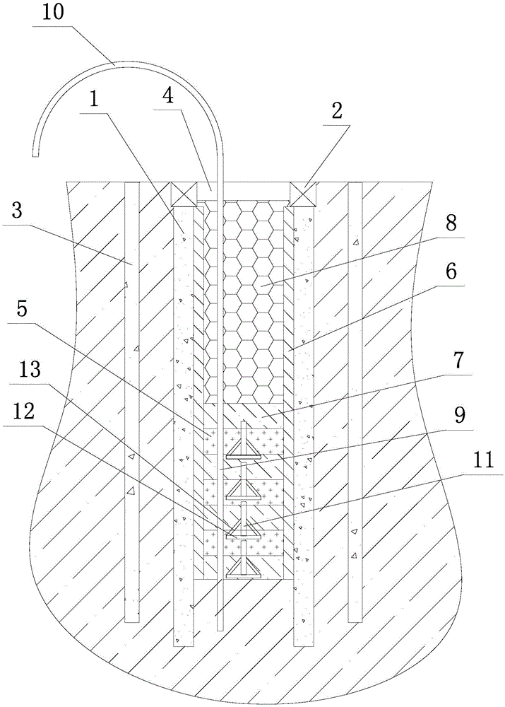
[0027] Such as figure 1 , figure 2 As shown, the shock-absorbing ditch with pressure relief device and shockproof plate of the present invention includes a circle of support piles 1 and a circle of pressure beams 2 that are poured on the top of each support pile 1 to connect each support pile 1 into a whole . The support pile 1 generally adopts the bored cast-in-place pile. The ring support piles 1 include two rows of support piles 1 extending along the length direction of the shock absorbing ditch and two rows of support piles 1 extending along the width direction of the shock absorbing ditch; the above four rows of support piles 1 are connected end to end in a circle, Constitutes the profile of the damping ditch.

[0028] The outer side of the ring support pile 1 is provided with a circle of cement-soil mixing pile 3 to form a water-stop...


PUM


Abstract

The invention discloses a damping ditch with a pressure relief device and shockproof plates and a construction method for the damping ditch. The damping ditch comprises a circle of support piles (1) and a circle of capping beam (2); the outer side of the circle of support piles (1) is provided with a circle of cement-soil mixing piles (3); top inner supports (4) are arranged at elevation positions of the capping beam (2); the inner side of each row of the support piles (1) extending along a length direction is connected with an edge shockproof plate (6); a pressure relief pipe (9) is also inserted into the bottom of the damping ditch; a damping particle layer is laid in the damping ditch from the bottom of the ditch to top; foam (8) is filled from the top part of the damping particle layer to a ground elevation; multiple rows of middle shockproof plates (11) different in layer height are buried in the damping particle layer; the key step of the construction method is that a process of laying the damping particle layer and a process of laying the middle shockproof plates (11) are performed in an integration manner. According to the damping ditch and the construction method thereof, water accumulation in the ditch can be avoided, depth can be greatly increased, and a damping and shock insulation effect is ideal.

Description

technical field [0001] The invention relates to the field of anti-shock construction in rock and soil, in particular to a shock-absorbing ditch with a pressure relief device and a shock-proof plate for separating the construction site from the surrounding environment during pile foundation construction to realize shock-absorbing or shock-proof functions and a construction method thereof . Background technique [0002] During pile foundation construction, vibrations are unavoidable during the process of compacting soil, crushing rock formations with impact hammers, and driving cranes and concrete tank trucks on the construction ground. This vibration will spread from the construction site to the surrounding environment, loosen the surrounding soil, and cause uneven settlement of the surrounding soil. This uneven settlement will cause the surrounding buildings to incline, or cause the underground pipelines buried in the surrounding soil to undergo rigid fracture and damage, w...

Claims


Application Information

Patent Timeline
Patent Type & Authority Applications(China)
IPC IPC(8): E02D31/08E02D19/06
CPCE02D19/06E02D31/08
Inventor 付连红徐新战陈保德何文强王喜叶兴友夏克玲教哲
Owner 浙江易通特种基础工程股份有限公司
Why Eureka
Try Eureka