
Super high rise steel structure building outrigger truss delay connection node and construction method

A technology of outrigger truss and delayed connection, which is used in buildings, building components, truss-type structures, etc., can solve problems such as tensile deformation, waste of outer frame columns, and tearing of weld seams, so as to prevent weld seams from being torn or pulled. deformation effect

Inactive Publication Date: 2016-05-04
CHINA CONSTR STEEL STRUCTURE CORP LTD
View PDF5 Cites 8 Cited by
  • Summary
  • Abstract
  • Description
  • Claims
  • Application Information

AI Technical Summary

Problems solved by technology

There are at least the following disadvantages in this scheme of using ordinary connection nodes: 1) Due to certain differences in the deformation of the inner and outer cylinders during the construction stage, premature welding and fixing of the outrigger truss nodes will cause most of the vertical load on the upper floor of the outrigger truss to be lost. The outrigger truss bears and cannot be transmitted downward through the outer frame columns, resulting in a serious waste of outer frame columns originally designed to mainly bear vertical loads
4) The weld at the node of the outrigger truss may be torn or deformed

Method used


Image

  • Super high rise steel structure building outrigger truss delay connection node and construction method
  • Super high rise steel structure building outrigger truss delay connection node and construction method
  • Super high rise steel structure building outrigger truss delay connection node and construction method

Examples


Embodiment Construction

[0027] The following clearly and completely describes the technical solutions in the embodiments of the present invention. Obviously, the described embodiments are only some of the embodiments of the present invention, but not all of them. Based on the embodiments of the present invention, all other embodiments obtained by persons of ordinary skill in the art without making creative efforts belong to the protection scope of the present invention.

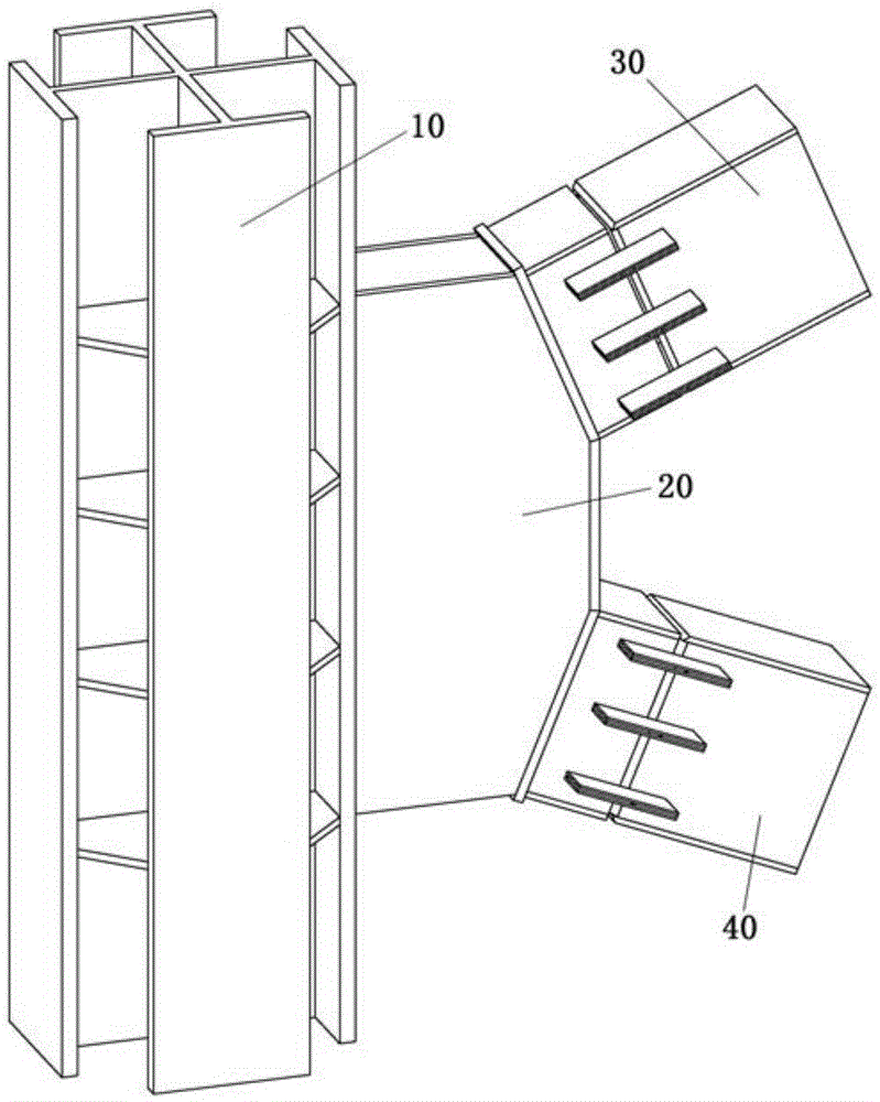
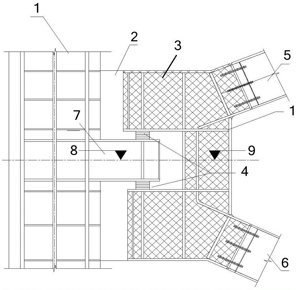
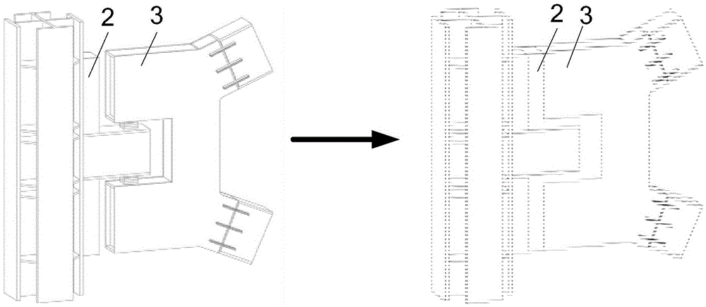
[0028] Such as figure 2 As shown, the embodiment of the present invention provides a delayed connection node of the outrigger truss of a super high-rise steel structure building, which is used to connect the outer frame column and the outrigger truss, including: U-shaped groove structural parts, two sets of steel backing plates and sealing plates;

[0029] Among them, the U-shaped groove structure is arranged horizontally, and the non-open end of the U-shaped groove is provided with two corbels that can be connected with the upper ...


PUM


Abstract

The invention discloses a super high rise steel structure building outrigger truss delay connection node and a construction method. The node comprises a U-shaped slot structure component which is arranged horizontally, wherein two brackets which can be connected with the upper and lower chords of an outrigger truss are arranged on the outside of a non-open end of a U-shaped slot respectively, and the width of the open end of the U-shaped slot of the U-shaped slot structure component is larger than that of an outside frame column bracket; two groups of steel cushion plates are arranged in the gaps between the upper end surface and the lower end surface of the outside frame column bracket and the open end of the U-shaped slot structure component respectively; an opening seal plate is formed by a U-shaped body arranged in the middle position and two extension edges which are connected and perpendicular to the outsides of two edges of the opening end of the U-shaped body, and the shape of the opening sealing plate is matched with the shapes of the gaps formed between the U-shaped slot structure component and the outside frame column as well as the outside frame column bracket. By the aid of the node, delay connection of the outrigger truss and the outside frame column can be realized, and the problem caused by early connection of the outrigger truss and the outside frame column in the construction initial stage is solved.

Description

technical field [0001] The invention relates to the field of steel structure building construction, in particular to a delayed connection node of an outrigger truss of a super high-rise steel structure building and a construction method. Background technique [0002] With the rapid development of the construction industry, super high-rise buildings over 300 meters continue to emerge. In super high-rise buildings where horizontal loads play a controlling role, setting outrigger trusses can improve the overall working performance of the structure, thereby improving the lateral stiffness of the structure under horizontal loads such as wind loads and earthquake loads, and controlling the top displacement and core of the structure. The overturning moment borne by the barrel. At present, super high-rise buildings over 300m at home and abroad generally adopt the "steel frame-core tube with outrigger truss" structural system. [0003] However, for the structural construction stage...

Claims


Application Information

Patent Timeline
Patent Type & Authority Applications(China)
IPC IPC(8): E04C3/11E04B1/58E04B1/98
CPCE04C3/11E04B1/58E04B1/98
Inventor 邵新宇段海杨正军汪晓阳张希博米裕李凌峰孔维拯
Owner CHINA CONSTR STEEL STRUCTURE CORP LTD
Features
  • Generate Ideas
  • Intellectual Property
  • Life Sciences
  • Materials
  • Tech Scout
  • Unparalleled Data Quality
  • Higher Quality Content
  • 60% Fewer Hallucinations
Learn More