
Roof ventilating device

A technology of ventilation equipment and side frame, applied in the field of roof ventilation equipment, can solve the problems of air pollution, toxic gas, affecting the health and safety of experimenters, etc., and achieve the effect of fast ventilation, high efficiency, and pollution avoidance.

Active Publication Date: 2016-05-04
韩佳倪 +1
View PDF6 Cites 3 Cited by
  • Summary
  • Abstract
  • Description
  • Claims
  • Application Information

AI Technical Summary

Problems solved by technology

[0002] In the process of chemical experiments, various unpleasant, corrosive, toxic or explosive gases are often produced. If these harmful gases are not discharged outside in time, they will cause air pollution in the chemical laboratory and affect the experimenters. health and safety; affects the accuracy and service life of instruments and equipment, therefore, laboratory ventilation is an indispensable part of laboratory design
In order to prevent laboratory workers from inhaling or swallowing some toxic, pathogenic or toxic chemicals and organisms, the laboratory should have good ventilation. Usually, the ventilation of chemical laboratories is often through doors and windows to the indoor and outdoor. The air is exchanged, and the smelly, corrosive, and toxic gases are replaced from the doors and windows. This replacement method is easy to pollute the aisles or office areas in non-experimental areas

Method used


Image

  • Roof ventilating device
  • Roof ventilating device
  • Roof ventilating device

Examples


specific Embodiment 1

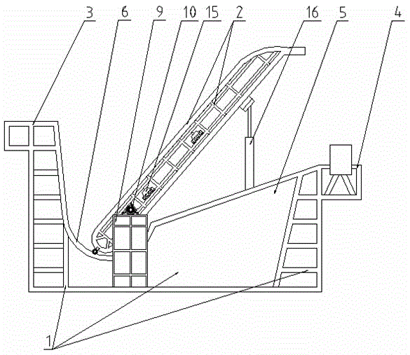
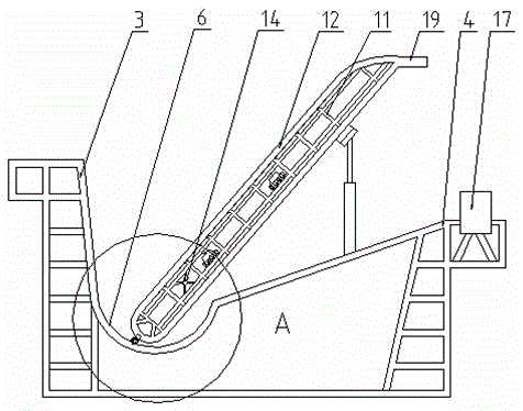
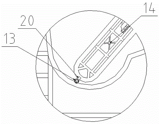
[0024] See Figure 1-Figure 5 Aiming at the problem of ventilation in a chemical laboratory, the present invention is a roof ventilation device, including a window frame 1 and a window sash 2. The window frame 1 includes a front frame 3, a rear frame 4, and a fixed connection between the front frame 3 and the rear frame 4. Side frame 5, side frame 5 is divided into front and rear, side frame 5 front and front frame 3 are fixedly connected, side frame 5 rear and rear frame 4 are fixedly connected, side frame 5 is sloped, side frame 5 A recess 6 is provided at the front slope, a guide rail 7 is provided in the recess 6, a rack 8 is provided in the guide rail 7, a bracket 9 is provided on both sides of the side frame 5, and a vertical seat bearing 10 is provided on the bracket 9;

[0025] The window sash 2 includes a frame 11 and a composite board 12 arranged inside and outside the frame 11. The window sash 2 includes a front end and a rear end. The front end of the window sash 2 is...


PUM


Abstract

The invention discloses a roof ventilating device, and belongs to the technical field of house ventilation. The roof ventilating device is characterized by comprising a window frame and a sash; the window frame comprises a front border, a rear border and a side border fixedly connected between the front border and the rear border, a pit is formed in the front portion of the side border and internally provided with guide rails, and racks are arranged in the guide rails, and supports are arranged at the two sides of the side border and each provided with a bearing with a vertical base; the sash comprises a front end and a rear end, gears are arranged at the front end of the sash, and a main shaft is arranged at the front end of the gravity center of the sash and is arranged in the bearings with the vertical bases. The roof ventilating device has the advantages that the sash can be opened or closed automatically and can rotate around the main shaft under the action of an electric lifting rod to be opened, the side border is designed to be provided with the pit structure, the front end of the sash can slide in the pit, the dead-angle ventilation mode can be achieved, and ventilation speed and efficiency are high.

Description

Technical field [0001] The invention relates to the technical field of house ventilation, in particular to a roof ventilation device. Background technique [0002] In the process of chemical experiments, various unpleasant, corrosive, toxic or explosive gases are often produced. If these harmful gases are not discharged outside in time, they will cause air pollution in the chemical laboratory and affect the experimenters. Health and safety; affect the accuracy and service life of instruments and equipment, therefore, laboratory ventilation is an indispensable part of laboratory design. In order to prevent laboratory staff from inhaling or swallowing some toxic, pathogenic or unidentified toxic chemicals and organisms, the laboratory should have good ventilation. Generally, the ventilation of chemical laboratories is often through doors and windows to indoor and outdoor The air is exchanged, and unpleasant, corrosive, and toxic gases are replaced from the doors and windows. This...

Claims


Application Information

Patent Timeline
Patent Type & Authority Applications(China)
IPC IPC(8): E06B3/36E06B1/36E06B7/02E06B7/16E06B3/68E05D1/04E05D1/06E04D13/035E04D13/16
CPCE04D13/0351E04D13/16E05D1/04E05D1/06E06B1/36E06B3/36E06B3/68E06B7/02E06B7/16E06B2007/023
Inventor 李沁心
Owner 韩佳倪
Learn More