
Combined thermal shielding structure for vertical pump for conveying high-temperature medium

A high-temperature medium and heat shielding technology, applied in the direction of non-variable pumps, non-volume pumps, special fluid pumps, etc., can solve the limited heat insulation effect of the vacuum chamber, the temperature rise of the sealing mechanism, and damage to the pump sealing structure, etc. problem, to achieve the effect of heat transfer performance

Active Publication Date: 2016-05-04
HEFEI INSTITUTES OF PHYSICAL SCIENCE - CHINESE ACAD OF SCI
View PDF6 Cites 3 Cited by
  • Summary
  • Abstract
  • Description
  • Claims
  • Application Information

AI Technical Summary

Problems solved by technology

When transporting some toxic or high-temperature substances that are prone to chemical reactions with air, water, etc., when the heat exchange tube breaks and the cooling medium flows into the pumping medium, it may cause explosions or dangerous accidents, or when the pumping medium is very expensive, replace The rupture of the heat pipe will pollute the pumped medium and cause huge economic losses. At this time, it is also necessary to strictly control the flow of external pollutants into the pumped medium
On the other hand, if only the vacuum chamber is used, when the temperature of the conveying medium changes, due to the limited heat insulation effect of the vacuum chamber, the temperature rise at the sealing mechanism after the heat shield may be too high, which may damage the sealing structure of the pump.

Method used


Image

  • Combined thermal shielding structure for vertical pump for conveying high-temperature medium
  • Combined thermal shielding structure for vertical pump for conveying high-temperature medium

Examples


Embodiment approach 1

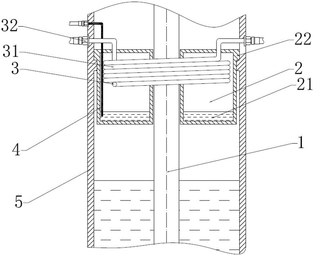
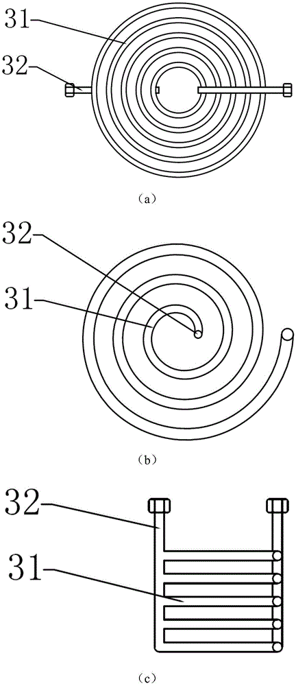
[0022] The main features of Embodiment 1 are: a combined heat shield structure for vertical pumps conveying high-temperature media, such as Figure 1-2 As shown, it includes a pump shaft 1 , a low-pressure heat pipe 2 , a forced circulation heat exchange device 3 , a liquid level gauge 4 and a pump casing 5 . The low-pressure heat pipe 2 includes a cooling medium 21 in the heat pipe wall and a heat pipe wall 22. The forced circulation heat exchange device 3 includes a heat exchange pipe 31 and a heat exchange pipe outlet 32. The heat shielding structure is installed in a vertical mechanical pump. It is a submerged pump for transporting high temperature liquid metal. The lower end of the heat shielding structure is a high-temperature liquid metal, and the upper end of the heat shielding structure is other components such as the shaft seal of the pump. The heat of the liquid metal at the lower end is transferred to the low-pressure heat pipe 2 of the heat-shielding structure. F...


PUM


Abstract

The invention discloses a combined thermal shielding structure for a vertical pump of conveying a high-temperature medium. The structure comprises a low-pressure heat pipe, a forced heat exchange pipe and a liquid level meter. A thermal shielding device is a combined structure of the forced heat exchange pipe and the low-pressure heat pipe. The forced heat exchange pipe is installed in the low-pressure heat pipe. A medium in the heat pipe is subjected to phase change after being heated, is condensed when ascending to the top end of a low-pressure cavity and meeting the heat exchange pipe, and falls to the bottom of the low-pressure cavity under the effect of gravity. When the heat exchange pipe is broken, the internal medium is leaked into the heat pipe, so that the medium in the heat exchange pipe is prevented from leaking into the pumped medium to cause pollution. The liquid level meter is mounted in the low-pressure cavity; and when the heat exchange pipe is broken, the liquid level rises, and the liquid level meter detects an ultrahigh liquid level signal and monitors if the heat exchange pipe is broken. When the temperature of the pumped medium is changed, the flow of a cooling medium in the heat exchange pipe is adjusted to realize adjustment of heat exchange quantity so as to guarantee such installed parts as a shaft seal after thermal shielding to be located at a relatively stable temperature.

Description

technical field [0001] The invention relates to the technical field of heat shielding structures of mechanical pumps, in particular to a combined heat shielding structure for vertical pumps conveying high-temperature media. Background technique [0002] For vertical submerged pumps that transport high-temperature media, in order to prevent heat from being transferred to the motor, a heat shield needs to be installed between the shaft seal and the hydraulic components. Generally, forced heat exchange tubes can be used to take away the transferred heat, or vacuum chambers can be used to isolate heat transfer. In vertical pumps used to transport liquid heavy metal lead-bismuth medium, in order to prevent contamination of the transported medium, it is strictly forbidden for external media to enter the transported medium. When the forced heat exchange tube is used for heat exchange, if the tube wall is damaged, the heat exchange fluid in the tube will leak into the lead-bismuth ...

Claims


Application Information

Patent Timeline
IPC IPC(8): F04D29/58F04D7/06
CPCF04D7/06F04D7/065F04D29/5866F04D29/588
Inventor 马旭丹李小龙黄群英高胜柳月静
Owner HEFEI INSTITUTES OF PHYSICAL SCIENCE - CHINESE ACAD OF SCI
Learn More