
Patsnap Eureka
For R&D, Patsnap Eureka makes reading and utilizing patents & technical documents easy.
Patsnap Eureka AIR
Designed for self-driven R&D workflows. Generate viable solutions, solve complex R&D challenges, empower your innovation with AI.

Patsnap Eureka Materials
Designed for material experts only. Revolutionize your material R&D, from search, analyze, to developing new materials.

TechResearch
Generate reliable direction feasibility study reports for your R&D in just a few steps.

TechSeek
Discover and master advanced knowledge NOW. Basics, ideas, possibilities, all at once.

TechMind
As an expert in R&D Theories, TechMind can generates customized viable solutions instantly.

TechRisk
Analyze your overall solution with one click, know your potential R&D risks in advance.

TechMonitor
Get weekly tech updates, stay abreast of the latest tech innovations and key insights.
Moment increasing energy storage flywheel
An energy storage flywheel and wheel cover technology, applied in the field of flywheels, can solve the problems of poor compatibility and heavy weight, and achieve the effects of convenient specification change, convenient manufacturing, and reduced driving energy
- Summary
- Abstract
- Description
- Claims
- Application Information
AI Technical Summary
Problems solved by technology
Method used
Image

Examples
Embodiment Construction
[0012] The present invention will be further described below in conjunction with the accompanying drawings and specific embodiments.
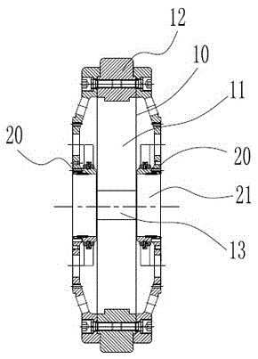
[0013] Such as figure 1 Shown, a kind of torque increasing energy storage flywheel, it comprises: counterweight rim 10 and wheel cover 20, described counterweight rim 10 comprises hollow cylindrical shell 11 and counterweight 12, described counterweight The block 12 is placed inside the casing 11 and connected to the circumferential surface of the casing 11. The casing 11 and the wheel cover 20 of the counterweight rim 10 are provided with through holes (13, 21) for the long axis to pass through. The counterweight rim 10 The left and right sides of the wheel are fixedly connected to the wheel cover 20 respectively, and the counterweight rim 10 and the wheel cover 20 rotate around a common axis. The assembly structure is adopted to facilitate the manufacture and replacement of different specifications, and to maximize the serialization of produc...
PUM
 Abstract
Description
Claims
Application Information
 - R&D Engineer
- R&D Manager
- IP Professional
- Industry Leading Data Capabilities
- Powerful AI technology
- Patent DNA Extraction
Browse by: Latest US Patents, China's latest patents, Technical Efficacy Thesaurus, Application Domain, Technology Topic, Popular Technical Reports.
© 2024 PatSnap. All rights reserved.Legal|Privacy policy|Modern Slavery Act Transparency Statement|Sitemap|About US| Contact US: help@patsnap.com