
Heat exchanger realizing pipe communication of heating pipes

A heating pipe and heat exchanger technology, applied in the field of HVAC, can solve the problems of small heat exchange area, low heat exchange efficiency and high cost of the heat exchanger, and achieve advanced technology, large heat exchange area and long service life Effect

Active Publication Date: 2016-05-04
山东利能换热器有限公司
View PDF5 Cites 3 Cited by
  • Summary
  • Abstract
  • Description
  • Claims
  • Application Information

AI Technical Summary

Problems solved by technology

In the prior art, the connecting pipe 6 is welded and connected to the orifice plate of the header, and the mouth of the connecting pipe 6 and the orifice plate of the header are in an open state in an I-shaped horizontal plane, which is convenient for inserting into the heat-absorbing pipe 4 as a whole or separately. In the existing technology, there are many materials used for the header orifice plate and the header shell plate, the welding volume of processing and manufacturing is large, and the cost is high. The mixed flow type of thermal fluid in the tube cavity cannot realize the countercurrent heat exchange of the present invention, resulting in low heat exchange efficiency and low cooling efficiency. source water flow is small
The existing technology is no longer suitable for heating with low-temperature heat sources, and the heat exchanger is eliminated due to its small heat transfer area and poor effect, which cannot continuously exchange hot water for bathing

Method used


Image

  • Heat exchanger realizing pipe communication of heating pipes
  • Heat exchanger realizing pipe communication of heating pipes
  • Heat exchanger realizing pipe communication of heating pipes

Examples


Embodiment Construction

[0027] The present invention will be further described below in conjunction with the accompanying drawings and specific embodiments.

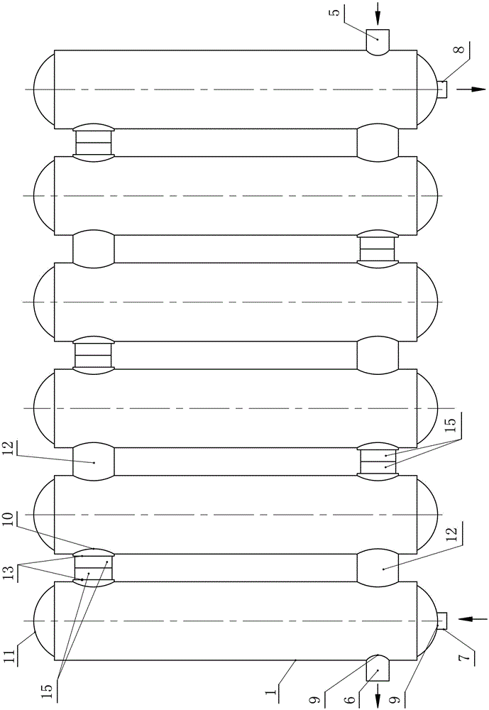
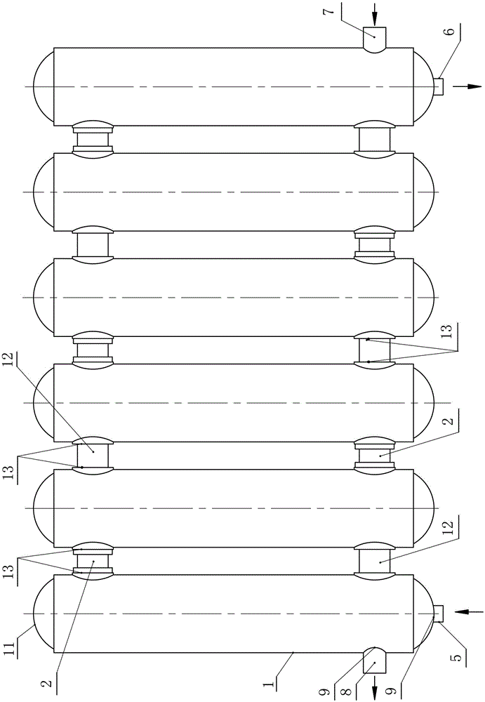
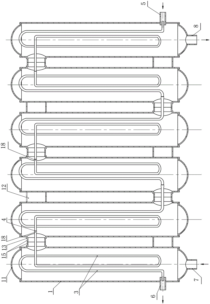
[0028] 1. The heating pipe of the present invention connects the heat exchanger such as Figure 1-18As shown, it includes: multiple heating pipes 1, end blocking plates 11, heating straight pipes 2, wall pipes 15, support members 12, cold water heat exchange pipes 3, notch connecting plates 22, pipe joint parts assembled and welded It is a heat exchanger in the shape of a radiator; some parts of the heat exchanger are provided with pipe joint welding ports 9 to facilitate the installation and welding of pipe joints; or some parts of the heat exchanger are not provided with pipe joint welding ports 9; Pipe joint Ⅳ8, cold water inlet pipe joint Ⅰ5, cold water outlet pipe joint Ⅱ6 and pipe joint welding port 9 on the heat exchanger parts are welded and connected to form a shell-side hot fluid channel or a tube-side cold fluid channel; it is charac...


PUM


Abstract

A heat exchanger realizing pipe communication of heating pipes is characterized in that pipe cavities of multiple heating pipes are communicated with one another; straight heating communication pipes are sequentially inserted into pipe communication weld holes in the multiple heating pipes for welding, series connection and communication, or the pipe cavities of the multiple heating pipes are welded and communicated directly through wall pull pipes, or small notches in walls of the multiple heating pipes are closed, welded and blocked by notch communicating plates, or the pipe wall, where the notches are formed, of each heating pipe is directly welded and communicated with the pipe wall, where the notches are formed, of the adjacent heating pipe, and then a circular heat transfer flow channel of a hot fluid is formed; at least one cold water heat exchange pipe is arranged in the pipe cavity of each heating pipe; or the cold water heat exchange pipe is coiled to form multi-ring bending pipes to be wholly inserted into the pipe cavities of the multiple heating pipes for overall communication. The heat exchange area is large, the cold water heat exchange pipe is coiled to form the multi-ring bending pipes to be wholly or separately inserted into the pipe cavities of the multiple heating pipes, joint welding communication of the bending pipes is adopted, the technology is advanced, the structure is compact, heat supply, heat dissipation and hot water exchange can be realized, the number of pipeline welding joints is reduced, the heat exchanger is not prone to water leakage, and the product service cycle is long.

Description

[0001] The invention relates to the field of heating and ventilating technology, and uses heating as a heat source to exchange hot water for office and household heating heat exchangers, in particular to a stainless steel or copper pipe heating pipe pipe-connected heat exchanger. Background technique [0002] The applicant applied for a patent on March 17, 2005 named "a countercurrent heat exchanger", the patent number is 200520081141.7, and the announcement number is CN2783244Y. The patent specification fails to make a clear and complete description. The claim lacks at least necessary technical features such as “blocking plate at the end or opening of the heat supply pipe, connection of the heat absorbing pipe to the elbow connection”, and the lack of these technical features will inevitably make the claim unclear and make it impossible for those skilled in the art to implement it. However, the necessary technical features are not written in the instructions, and there is a de...

Claims


Application Information

Patent Timeline
IPC IPC(8): F28D1/053F28F9/26
CPCF28D1/05308F28F9/268F28F2275/06
Inventor 张伟张冲
Owner 山东利能换热器有限公司
Features
  • Generate Ideas
  • Intellectual Property
  • Life Sciences
  • Materials
  • Tech Scout
  • Unparalleled Data Quality
  • Higher Quality Content
  • 60% Fewer Hallucinations
Learn More