Reflector adjusting method of laser rotary table

An adjustment method and mirror technology, applied in optics, optical components, installation, etc., can solve problems such as laser interference, inaccurate irradiation position, and low tracking accuracy, and achieve improved tracking accuracy, improved emission pointing accuracy, and high adjustment accuracy Effect

Inactive Publication Date: 2016-05-04
HEBEI HANGUANG HEAVY IND
View PDF6 Cites 9 Cited by
  • Summary
  • Abstract
  • Description
  • Claims
  • Application Information

AI Technical Summary

Problems solved by technology

[0004] The quality of the orthogonality adjustment of the laser mirror directly determines the effect of laser interference countermeasures. If the adjustment is not good, it will lead to inaccurate irradiation positions and low tracking accuracy.

Method used


Image

  • Reflector adjusting method of laser rotary table
  • Reflector adjusting method of laser rotary table
  • Reflector adjusting method of laser rotary table

Examples


Embodiment Construction

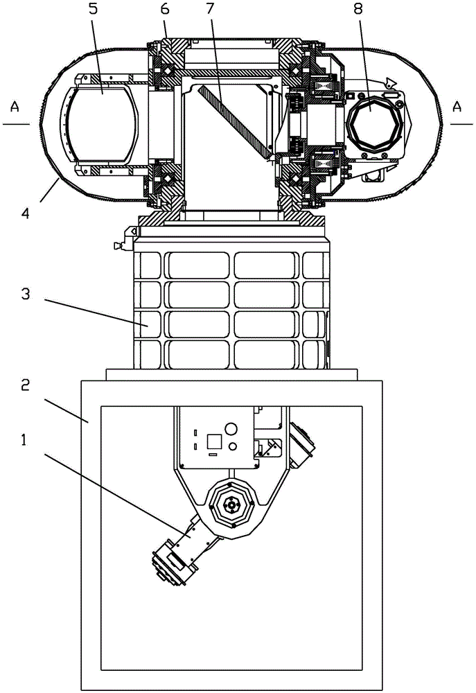
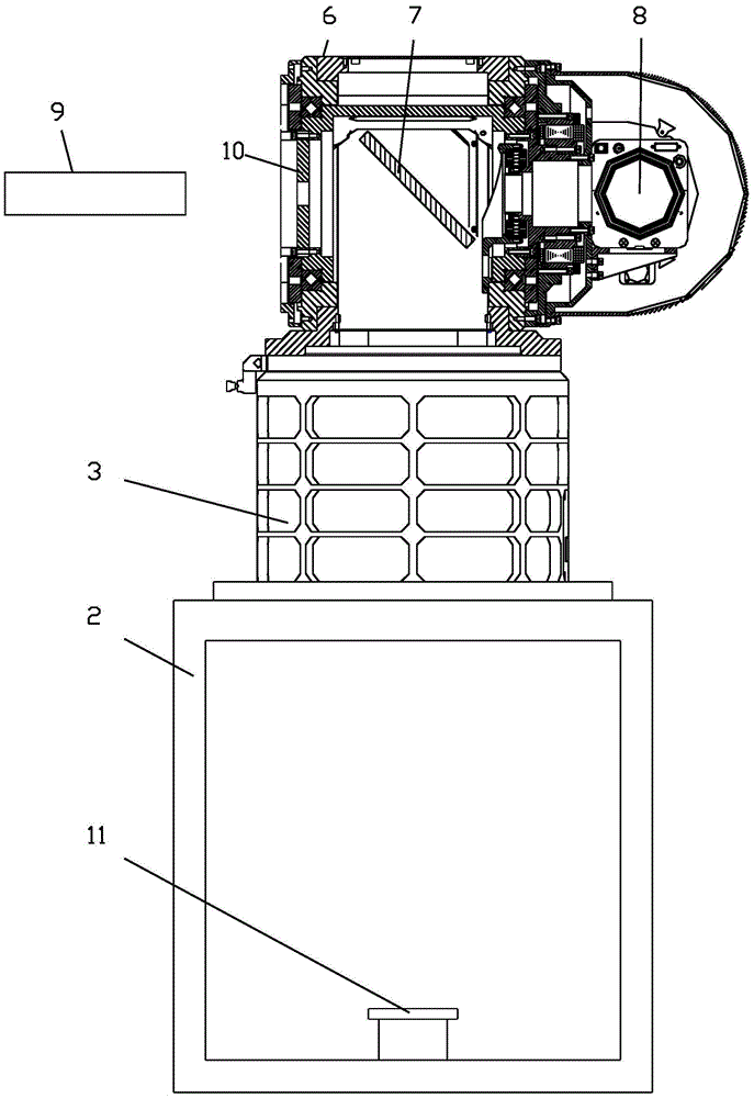
[0015] The present invention comprises the following steps: 1), adjust the third reflector 7: remove the first reflector 1 and the second reflector 5, the first frock reflector 10 is fixed on the left end face of the laser turntable 6, turn the laser turntable For the pitch axis, adjust the first tooling reflector 10 to be perpendicular to the pitch axis, adjust the azimuth seat 3 to be horizontal, place the second tooling reflector 11 under the azimuth seat 3 and adjust the level, use the collimator 9 to observe the reflection through the third reflector 7 Image, adjust the third reflector 7 to make the reflected image coincide with the crosshairs of the collimator 9, remove the first frock reflector 10, and the adjustment of the third reflector 7 is completed, as figure 1 , 2 shown.

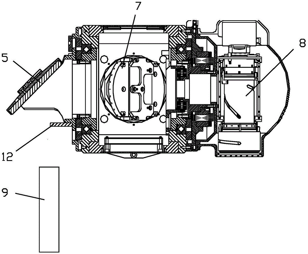
[0016] 2), adjust the second reflector 5: install the second reflector 5 on the left end surface of the laser turntable, stick the third frock reflector 12 on the front end of the fixing frame...


PUM


Abstract

The invention relates to a reflector adjusting method of a laser rotary table. The method comprises the following steps that 1) a third reflector is adjusted by fixing a first tool reflector at the left end surface of the laser rotary table and adjusting the third reflector so that a reflection image coincides with a cross wire of a parallel light pipe; 2) a second reflector is adjusted by mounting the second reflector at the left end surface of the laser rotary table, pasting a third tool reflector to the front end surface of a second reflector fixing rack so that a reflection image of the third tool reflector coincides with the cross wire of the parallel light pipe; 3) a first reflector is adjusted by arranging the first reflector on a horizontal platform and placing a second tool reflector under a central hole of the first reflector that a reflection image coincides with the cross wire of the parallel light pipe; and 4) the first reflector is mounted by placing the parallel light pipe in front of the first reflector and using left and right pentaprisms, so that light is reflected into a sighting piece of a TV set and the sighting piece is adjusted to coincide with the cross wire of the parallel light pipe.

Description

technical field [0001] The invention relates to a reflector adjustment method, in particular to a reflector adjustment method for a laser turntable, which is used for a display console required by the navy to resist harsh environments. Background technique [0002] Since infrared-guided air-to-air or air-to-ground missiles are mostly medium-wave infrared, the laser jamming countermeasure system must work in the medium-wave infrared band to achieve the goal of jamming and blinding these incoming missiles. Because in order for the laser launch system to interfere and blind the infrared detectors of incoming missiles, it must have an optical path that can lock and track the target stably. However, due to the large inertia characteristic of the two-axis tracking turntable, it is difficult to achieve ultra-high precision and stable tracking of the target. Therefore, adding a small-inertia fine tracking turntable to the two-axis rough tracking turntable can provide laser emission ...

Claims


Application Information

Patent Timeline
Patent Type & Authority Applications(China)
IPC IPC(8): G02B27/62G02B7/182
CPCG02B7/182G02B27/62
Inventor 徐宗波李雷雷周隆梅
Owner HEBEI HANGUANG HEAVY IND
Why Eureka
Try Eureka