Pressure sensing touch control module

A touch module and pressure-sensing technology, applied in instruments, electrical digital data processing, data processing input/output process, etc., can solve the problems of complex manufacturing process and high cost, achieve accurate calculation results, save costs, and save electric energy The effect of consumption

Active Publication Date: 2016-05-04
TPK UNIVERSAL SOLUTIONS
View PDF4 Cites 31 Cited by
  • Summary
  • Abstract
  • Description
  • Claims
  • Application Information

AI Technical Summary

Problems solved by technology

[0003] In order to overcome the problems of high cost and complicated manufacturing process in which different ICs are used for the pressure sensing touch module in the prior art to separately collect the tou

Method used


Image

  • Pressure sensing touch control module
  • Pressure sensing touch control module
  • Pressure sensing touch control module

Examples


Embodiment Construction

[0031] In order to make the purpose, technical solutions and advantages of the present invention more clear, the present invention will be further described in detail below in conjunction with the accompanying drawings and implementation examples. It should be understood that the specific embodiments described here are only used to explain the present invention, not to limit the present invention.

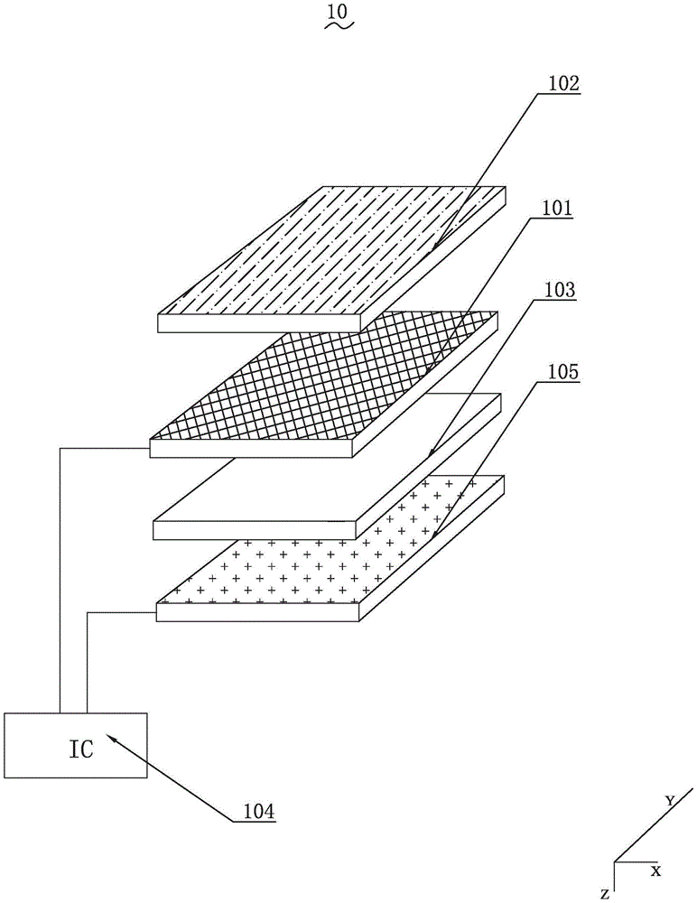
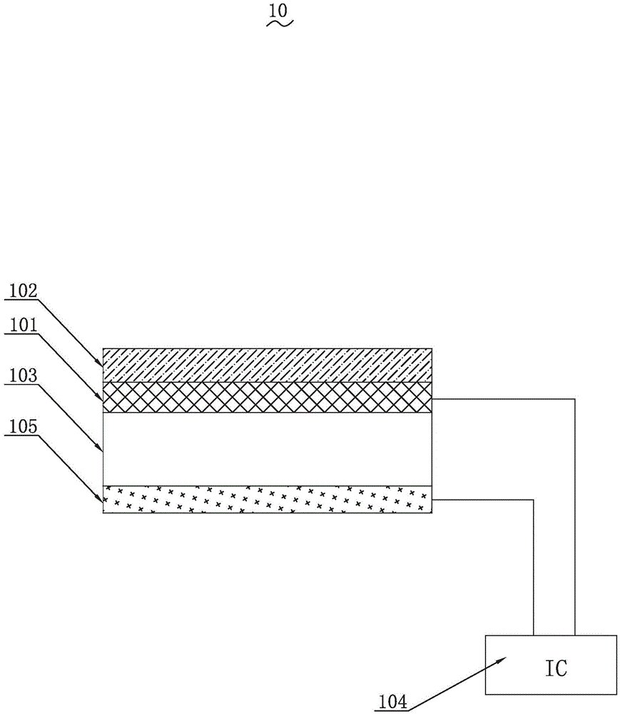
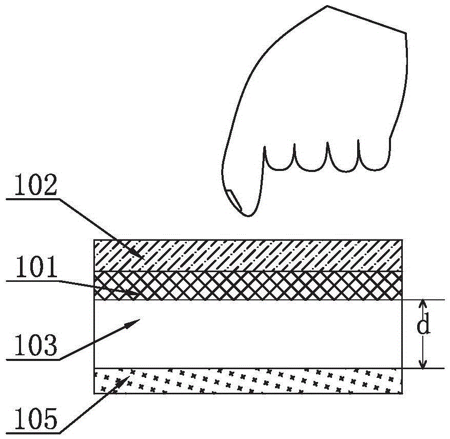
[0032] see figure 1 and figure 2 , the present invention is a pressure-sensing touch module 10 , which includes a cover plate 102 , a touch-sensing layer 101 , a first optical adhesive layer 103 and a conductive layer 105 . The cover plate 102 includes upper and lower surfaces, the upper surface is a touch surface, and the touch sensing layer 101 is disposed on a side away from the touch surface. The cover plate 102 mainly protects other laminated structures and circuits disposed thereunder. The first optical adhesive layer 103 is disposed between the touch sensing layer 101 an...


PUM

PropertyMeasurementUnit
Young's modulusaaaaaaaaaa
Thicknessaaaaaaaaaa
Young's modulusaaaaaaaaaa

Abstract

The invention provides a pressure sensing touch control module, comprising a touch control sensing layer and a conductive layer; the touch control sensing layer detects a touch control position signal at a first stage; the touch control sensing layer matches with the conductive layer at a second stage; two pole plates of a capacitor are formed through the touch control sensing layer and the conductive layer; pressure signals are detected according to the capacitance value change conditions generated according to the distance changes between the two pole plates. According to the module of the invention, the problems that the pressure sensing touch control module in the prior art collects the touch control position signals and the touch control pressure signals respectively, the cost is high and the preparation process is complex are solved; the pressure sensing touch control module of the invention detects the touch control position signals and the touch control pressure signals by a same IC at separate time.

Description

【Technical field】 [0001] The invention relates to the field of touch modules, in particular to a pressure-sensing touch module. 【Background technique】 [0002] At present, most touch panels on the market only have touch position detection. With the diversification of functions of electronic products, more and more usage scenarios need to detect the force at the touch point to complete more product functions. , to improve user experience, and in the existing capacitive pressure touch structure, an air layer is required to separate the two electrode structures. Because the resistance of the air layer is small, it can produce large deformation, but if the air layer exists Above the display, there may be a problem that the Newton ring affects the visual effect, so the pressure-sensing structure must be placed below the display, and this setting makes the pressure-sensing structure and the touch surface far away, and there are many other laminated structures in the middle to disp...

Claims


Application Information

Patent Timeline
IPC IPC(8): G06F3/041G06F3/044
Inventor 周家麒林尚宇庄志成黄俊荣林松柏唐骐
Owner TPK UNIVERSAL SOLUTIONS
Why Eureka
Try Eureka