A Hybrid Excitation Flux Switching Motor

A magnetic flux switching motor and hybrid excitation technology, applied in electrical components, electromechanical devices, magnetic circuit static parts, etc., can solve the problems of poor magnetic adjustment effect, reducing torque density, reducing power density and torque density, etc. Achieve the effect of increasing electromagnetic load, reducing rotor size and improving power density

Active Publication Date: 2017-11-17
JIANGSU UNIV
View PDF7 Cites 4 Cited by
  • Summary
  • Abstract
  • Description
  • Claims
  • Application Information

AI Technical Summary

Problems solved by technology

For example, the motor disclosed in the Chinese Patent Publication No. CN101277053A and titled "Hybrid Excitation Flux Switching Motor" has good magnetic modulation performance, but at the cost of reducing the volume of the permanent magnet, the field winding is added, which is impossible Avoid reducing the power density and torque density, etc.
The motor disclosed in the Chinese Patent Publication No. CN104539125A and titled "A Hybrid Excitation Flux Switching Motor" has good magnetic modulation performance, but at the expense of reducing the number of turns of the armature coil, the addition of the field winding also reduces the Torque density
More importantly, both of these two public hybrid excitation flux switching motors use DC excitation to directly adjust the permanent magnetic field, and the magnetic adjustment effect is poor.

Method used


Image

  • A Hybrid Excitation Flux Switching Motor
  • A Hybrid Excitation Flux Switching Motor
  • A Hybrid Excitation Flux Switching Motor

Examples


Embodiment Construction

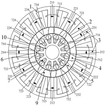
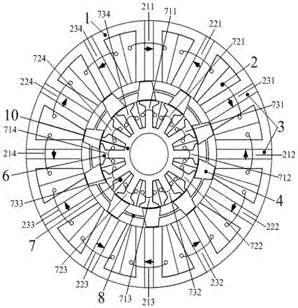
[0016] see figure 1 , the motor structure of the present invention includes an outer stator, a rotor and an inner stator. The inner stator is coaxially sleeved with the rotor, and the outer rotor is coaxially sleeved with the outer stator. There are radial air gaps between the rotor, the inner stator and the outer stator.

[0017] The outer stator is composed of an outer stator core, a permanent magnet 3 and a three-phase armature winding 2. The material of the permanent magnet 3 is selected from other types of permanent magnet materials such as NdFeB or ferrite. Among them, the outer stator core is composed of 12n U-shaped conductive cores 1, where n is an integer, and n≥1. The U-shaped magnetic core 1 is made of silicon steel sheets. The U-shaped notch of the U-shaped conductive magnetic core 1 faces the axis of the outer stator, and the two side walls of the U-shaped of the U-shaped conductive magnetic core 1 are the outer stator teeth. There are 12n U-shaped conductive...


PUM


Abstract

The invention discloses a hybrid excitation flux switching motor. The motor comprises an outer stator, a rotor and an inner stator. The rotor coaxially sheaths outside the inner stator. The outer stator coaxially sheaths outside the rotor. The outer stator comprises an outer stator iron core, permanent magnets and a three-phase armature winding. A three-phase alternating current excitation winding sheaths on convex pole teeth of an inner stator iron core. The quantity of the convex pole teeth of the inner stator iron core is equal to the quantity of the permanent magnets. The radial central axes of the convex pole teeth of the inner stator iron core and the radial central axes of the permanent magnets coincide. In the prior art, the excitation winding is placed by reducing the volume of the permanent magnet or reducing the number of turns of the armature winding. Through adoption of the hybrid excitation flux switching motor, the problem in the prior art is solved, the electromagnetic load of the motor is increased, a symmetrical three-phase alternating current with adjustable amplitude accessed to the inner stator excitation winding can generate a rotating magnetic field with adjustable amplitude and polarity, and the rotating magnetic field and an effective air gap magnetic field in a permanent magnetic field are overlaid, so that effective harmonic component in the permanent magnetic field is enhanced or weakened, so as to realize magnetic shunt operation.

Description

technical field [0001] The invention belongs to the fields of electricians and motors, and relates to a permanent magnet motor with strong torque output capability and high power density, in particular to a hybrid excitation magnetic flux switching motor. Background technique [0002] The magnetic flux switching motor is a stator permanent magnet motor. The stator permanent magnet motor places both permanent magnets and armature windings on the stator. The rotor is only an iron core with salient poles. The rotor has no windings, no slip rings and no rotors. brush. Compared with the rotor permanent magnet motor, the stator permanent magnet motor has the advantages of simple rotor structure, convenient permanent magnet cooling and high power density. The permanent magnets and armature windings of the flux-switching motor are located on the stator, and the rotor has neither permanent magnets nor windings. It has the characteristics of simple structure, reliable operation, easy...

Claims


Application Information

Patent Timeline
Patent Type & Authority Patents(China)
IPC IPC(8): H02K1/14H02K1/17H02K3/28H02K16/04
CPCH02K1/14H02K1/17H02K3/28H02K16/04H02K2213/03
Inventor 杜怿孙延东朱孝勇肖凤全力王晓兵王珲张庆李亚宁
Owner JIANGSU UNIV
Why Eureka
Try Eureka