
Auxiliary current transformer

An auxiliary converter and transformer technology, applied in the field of rail transit, can solve the problems of poor heat dissipation effect of the end components of the air duct, inconvenient cleaning of the air duct, large wind resistance, etc. The effect of air volume

Active Publication Date: 2016-05-04
ZHUZHOU CSR TIMES ELECTRIC CO LTD
View PDF6 Cites 3 Cited by
  • Summary
  • Abstract
  • Description
  • Claims
  • Application Information

AI Technical Summary

Problems solved by technology

However, the auxiliary converter generally has a large power, so the product has very high heat dissipation requirements
At present, the traditional auxiliary converter air duct design belongs to the series air duct, which mainly controls the total air intake by adjusting the size of the total air inlet, but the disadvantage is that the method of adjusting the total air volume is single, and due to the long air duct, Larger, resulting in poor heat dissipation effect of the end devices of the air duct, and the air duct is not easy to clean

Method used


Image

  • Auxiliary current transformer
  • Auxiliary current transformer
  • Auxiliary current transformer

Examples


Embodiment Construction

[0024] The present invention will be further described below in conjunction with the accompanying drawings and specific embodiments.

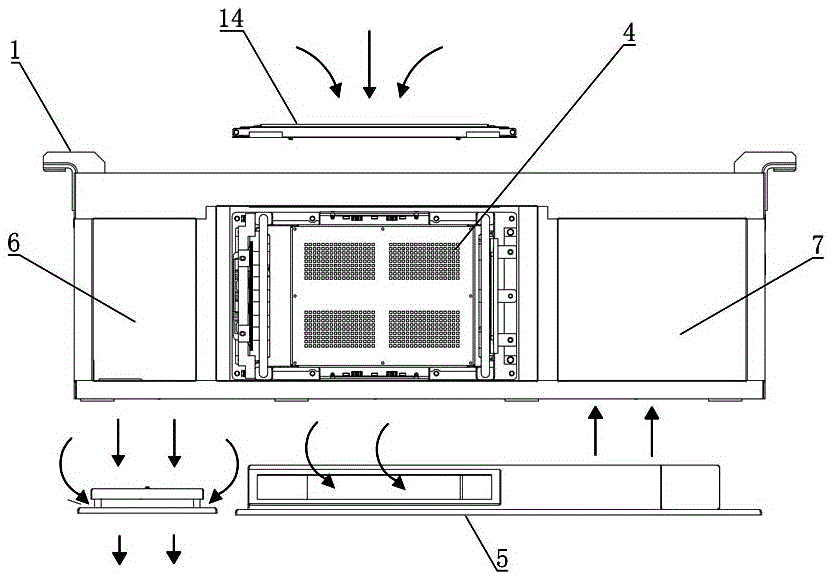
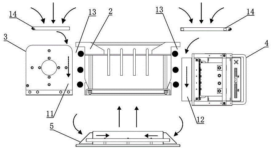
[0025] Such as Figure 1 to Figure 7 As shown, the auxiliary converter of this embodiment includes a cabinet body 1, a transformer 2, a reactor 3, an inverter 4 and an exhaust assembly 7 are installed in the cabinet body 1, and the reactor 3 and the inverter 4 are respectively installed on opposite sides of transformer 2 (eg image 3 and Figure 4 As shown, they are respectively located on the front and rear sides of the transformer 2), and the exhaust assembly 7 is installed on the side of the transformer 2 adjacent to the reactor 3 (such as Figure 4 shown, located on the right side of the transformer 2); the gap between the reactor 3 and the cabinet 1 and the gap between the reactor 3 body form the first air inlet channel 11 for the top air intake, and the gap between the inverter 4 and the cabinet 1 The gap between the transformer 2 and ...


PUM


Abstract

The invention discloses an auxiliary current transformer, comprising a cabinet body; a transformer, an electric reactor, an inverter and an exhaust air assembly are installed in the cabinet body; the electric reactor and the inverter are respectively installed at relative sides of the transformer; the exhaust air assembly is installed at the side of the transformer adjacent to the electric reactor; a first air inlet channel is formed between the electric reactor and the cabinet body; a second air inlet channel is formed between the inverter and the cabinet body; an exhaust air channel is formed between the transformer and the cabinet body; an air guide assembly is arranged at the bottom of the cabinet body; the air inlet of the air guide assembly is connected with the first air inlet channel and the second air inlet channel; the air outlet is connected with the air inlet of the exhaust air assembly; the air outlet of the exhaust air assembly aligns to the air inlet of the exhaust air channel; the side in the transformer relative to the exhaust air assembly is equipped with an exhaust air cavity; the air inlet of the exhaust air cavity is connected with the air outlet of the exhaust air channel; and the air outlet of the exhaust air cavity is arranged downward. The auxiliary current transformer of the invention is advantaged by simple and compact structure and adjustable air inlet quantity and air speed.

Description

technical field [0001] The invention mainly relates to the technical field of rail transit, in particular to an auxiliary converter. Background technique [0002] In forced air-cooled auxiliary converter products, air duct design is an extremely critical link in product design. If the air duct design is unreasonable, it will directly lead to an increase in device temperature, a decrease in life, and a decrease in reliability, which will eventually lead to device damage. or the product does not work properly. At present, the auxiliary converter cabinet is usually installed at the bottom of the train, and its installation space is very limited, especially the top air intake space is very small. However, the power of the auxiliary converter is generally large, so the product has very high requirements for heat dissipation. At present, the traditional auxiliary converter air duct design belongs to the series air duct, which mainly controls the total air intake by adjusting the...

Claims


Application Information

Patent Timeline
IPC IPC(8): H02M1/00H05K7/20
CPCH02M1/00H05K7/20
Inventor 饶东杰魏周艳刘清程超龙言青魏培华李志杰王明黄芳军耿志东
Owner ZHUZHOU CSR TIMES ELECTRIC CO LTD
Learn More