
Elevating equipment multi-direct current motor synchronous controller and method based on CAN bus
A technology of CAN bus and synchronous controller, applied in the field of DC motor synchronous control device, to achieve the effect of easy network operation, simple disassembly and assembly, and easy expansion
- Summary
- Abstract
- Description
- Claims
- Application Information
AI Technical Summary
Problems solved by technology
Method used
Image

Examples
Embodiment Construction
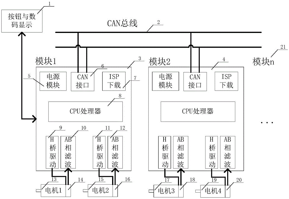
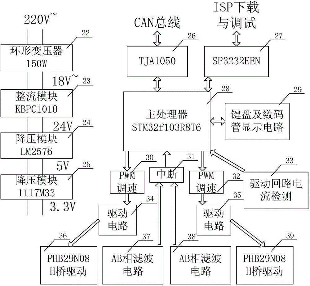
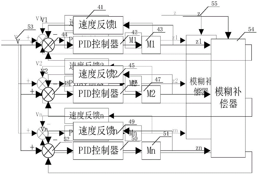
[0044] see Figure 1 to Figure 4 As shown, a CAN bus-based multi-DC motor synchronous controller for lifting equipment includes buttons for display and operation external to the controller and a digital display module 1, for receiving user instructions and operations, and feeding back to the main control The module motor controls and drives the first module 3, which realizes the expansion and synchronization of multiple modules on the CAN bus 2. The main control module motor controls and drives the first module 3 to the main control module through the CAN bus 2. The second module 4 sends a running command signal and coordinates the movement of each motion control module. The button and the digital display module 1 are electrically connected to the main control module motor control and drive first module 3 in two directions. The main control module motor controls and drives the first The two ends of the module 3 and the main control module motor control and drive second module 4 ...
PUM
 Abstract
Description
Claims
Application Information