
Shaped composite adsorbent material

a composite adsorbent and fluid stream technology, applied in the field of composite adsorbents or devices, can solve the problems of inability to recognize a shaped composite solution to the problem, inability to treat acc substrates, and inability to meet the requirements of adsorption, so as to maximize the surface area of the particulate adsorbent material, improve the access to the particulate material, and increase the accessibility of the adsorbent material

Inactive Publication Date: 2005-09-29
CALGON CARBON
View PDF22 Cites 10 Cited by
  • Summary
  • Abstract
  • Description
  • Claims
  • Application Information

AI Technical Summary

Benefits of technology

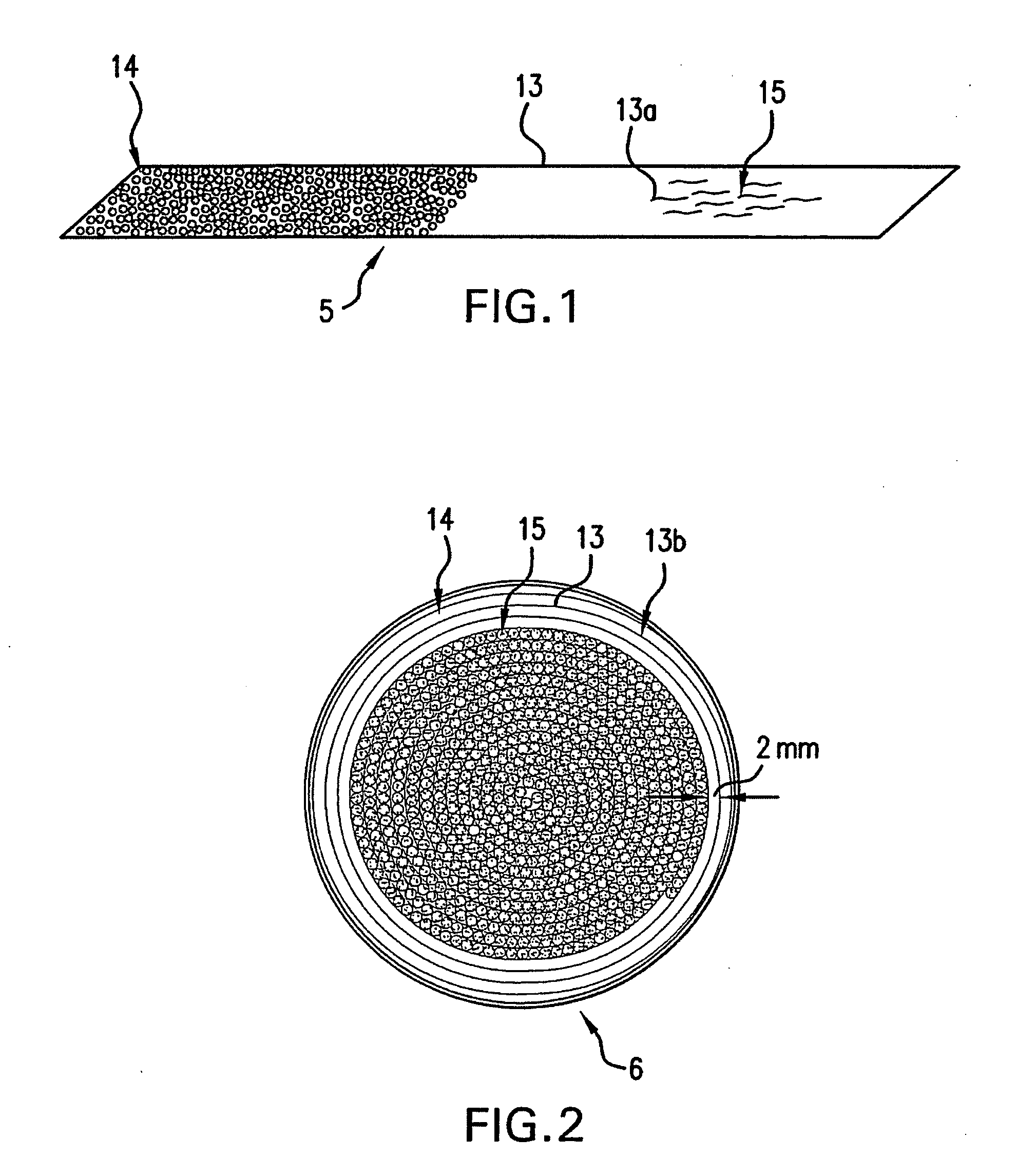
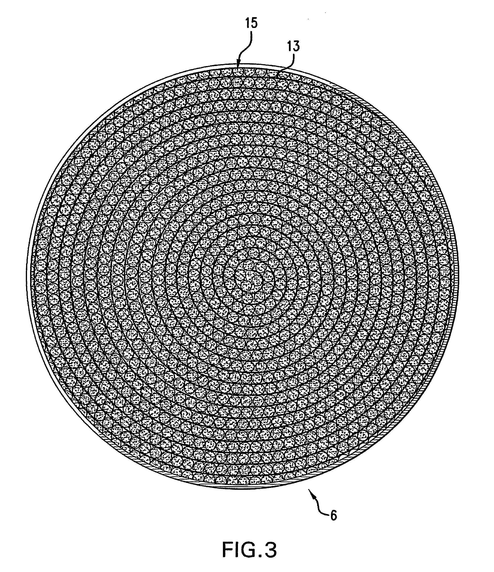
[0008] The present invention represents a substantial advance over prior composite adsorbents or devices. The present invention requires a substrate shaped into a spiral, disc, cylinder, or otherwise folded over on itself. The composite can also be in the form of a stack of strips or sheets. In any of these forms, this novel composite provides an advantage in that it improves access to the particulate material by comparison to a packed bed of material. It does so for example by providing a layer of particulate material along a substrate which thereby opens up the packed bed and increases the accessibility of the adsorbent material to the contaminants to be removed from the stream. Because only a minimal amount of the surface area of the particulate is used to secure it to the substrate, the capacity of the particulate remains close to that of bulk material particulate.
[0009] The current invention does not require the application of spray adhesives or the handling of powders to realize the advantages of maximizing the surface area of the particulate adsorbent material as required by traditional devices. Thus, dusting is also minimized by the immobilization of the particulate material. Unlike traditional devices, the invention uses a unique substrate comprised of a non-porous material. In an embodiment, the present invention has the further advantage that the adsorbent composite is used in a device having a form that is more practical to handle, more space efficient, and more attractive for a consumer product. Because of the unique construction, this composite can realize high adsorption capacity, fast adsorption kinetics, high volume capacity, low dusting, low pressure drop, and low cost.

Problems solved by technology

Such an arrangement, however, decreases the accessibility of the adsorbent to the fluid stream to be treated.
In both cases, the ACC substrate is a cost prohibitive material.
Although it notes the advantages of minimizing the pressure drop, the inventor does not recognize a shaped composite solution to the problem.
However, without reliance on a porous substrate, this device could not function as described.

Method used


Image

  • Shaped composite adsorbent material
  • Shaped composite adsorbent material
  • Shaped composite adsorbent material

Examples


example 1

[0030] An adsorbent device was created by pressing the adhesive side of a strip of ½″ SCOTCH® Magic™ Tape 810 into a tray of granular carbon and completely coating the adhesive with the carbon. The substrate tape measured 113 linear inches. The carbon was a U.S. 20×45 mesh BLP granular activated carbon from Calgon Carbon Corporation having an apparent density of 0.540 g / cc. The coated composite was wound into a tight spiral measuring about 3.5 inches in diameter to create a spiral adsorbent composite. The spiral was enclosed in an air permeable, disc-shaped prototype housing 18, as shown for example in FIG. 6. Housing 18 has air permeable faces 19 on both the front and back sides of the disc. Tests were conducted on this prototype unit. The carbon density of the spiral composite was 0.181 g / cc. This density was selected to optimize a balance between increasing access to the carbon while maintaining a high volumetric carbon density. As a result faster adsorption kinetics were obtaine...

example 2

[0036] In another experiment, the pressure drop was measured for a constant mass of 8.93 grams of carbon in the forms of a spiral composite, and a packed bed of bulk carbon. The spiral composite opens up the carbon bed and immobilizes the carbon in space thereby lowering the pressure drop across the bed. The bulk carbon bed was prepared to have a bed depth of 1.7 cm while the spiral composite spread the same amount of carbon out to a bed depth of 3.0 cm. This test demonstrated that a result of spreading the carbon bed out provided a significant reduction in the pressure drop of the bed. The test was conducted using 80 ppm butane in an air stream at 50% relative humidity and 0.6 m / sec linear velocity. The pressure drop of the packed bed of carbon was 1.010 inches of water while the pressure drop with the spiral construction bed was 0.095 inches of water. This represents a 10 fold decrease in the pressure drop which is desirable for many applications. The lower pressure drop is desira...

example 3

[0037] The flow rate of water through a water column was used to demonstrate the reduced pressure drop of the current invention with a liquid system. Using only gravity, a 9 inch water column was allowed to drain through the carbon bed and out of the column. Each column contained 238 grams of activated carbon. The column with the packed bed drained in 22.2 seconds and the column with the spiral composite carbon bed drained in 17.5 seconds. The result is a 21% increase in flow rate. This rate was achieved without addition of any pumps.


PUM

PropertyMeasurementUnit
widthaaaaaaaaaa
diameteraaaaaaaaaa
diameteraaaaaaaaaa

Abstract

A composite adsorbent includes a substrate to which an adsorbent material has been immobilized. The composite adsorbent is designed to be shaped into a variety of forms that provide a high adsorption capacity, low pressure drop, high volume capacity, and fast adsorption kinetics to effectively adsorb contaminants. Optionally, the composite adsorbent is also used in combination with an air permeable unit wherein it is advantageously positioned to provide enhanced adsorption of contaminants found in gas phase.

Description

RELATED PATENT APPLICATION [0001] This is a continuation in part of U.S. patent application Ser. No. 10 / 807,375 filed Mar. 23, 2004 entitled Spiral Composite Adsorbent Material.FIELD OF INVENTION [0002] This invention relates to a composite for the treatment of a fluid stream, and more particularly, to a shaped composite adsorbent or device containing a shaped composite adsorbent. BACKGROUND OF THE INVENTION [0003] Devices containing adsorbent materials for removing contaminants from fluid streams are known. Such devices may remove odors or purify ambient air. Some are used to remove contaminants from commercial and industrial gas streams. Others are used remove contaminants from liquid streams. The current invention can be used with any solid material. Typically these devices include an adsorbent material such as calcium phosphate, sodium bicarbonate powder, baking soda, silicas, aluminas, zeolites, or charcoal or carbon particles, wherein the adsorbent is provided as a bed of pack...

Claims


Application Information

Patent Timeline
Patent Type & Authority Applications(United States)
IPC IPC(8): B01J20/28B01J20/32
CPCB01D53/02B01D2253/25B01D2253/34B01J20/28026B01J20/3223B01J20/28033B01J20/28035B01J20/28052B01J20/32B01J20/2803B01J20/3204B01J20/321B01J20/3212B01J20/3236B01J20/3238B01J20/324B01J20/3268
Inventor DOUGHTY, DAVID T.COBES, JOHN W.
Owner CALGON CARBON
Learn More