
LTE (Long Term Evolution) system interference coordination method

A coordination method and technology of system interference, applied in transmission system, radio transmission system, diversity/multi-antenna system, etc., can solve the problem of poor multi-user diversity effect of the system, unable to obtain the best system performance, unable to obtain the best system performance, etc. question

Inactive Publication Date: 2016-05-04
CHINA INFOMRAITON CONSULTING & DESIGNING INST CO LTD +1
View PDF5 Cites 0 Cited by
  • Summary
  • Abstract
  • Description
  • Claims
  • Application Information

AI Technical Summary

Problems solved by technology

If cell 1 is assigned the frequency of the first subband, but if the edge users of cell 1 can obtain a higher SNR in subbands ranging from 4 to 15, then the edge users cannot obtain the optimal frequency resource on the allocated frequency resources. best system performance
At the same time, if a user in the center can obtain a higher signal-to-noise ratio on subbands 1 to 3, after allocating resources through the soft frequency multiplexing mechanism, a user in the center cannot obtain the best system performance.
Therefore, the system cannot obtain considerable multi-user diversity gain
[0014] Moreover, when the cell is heavily loaded by edge users, that is, when the traffic volume at the edge of the cell is large, the allocation of mutually orthogonal primary subcarriers to different cells will still increase the frequency reuse factor between cells, that is, the value of X Gradually increasing, the available frequency bands for central users are gradually decreasing, and the system spectrum utilization rate is severely reduced
[0015] From the above discussion, it can be known that under the soft frequency reuse mechanism, the multi-user diversity effect of the system is poor, and when the edge traffic is large, the spectrum utilization rate is low, and the system performance, especially the performance of the edge users, is not ideal

Method used


Image

  • LTE (Long Term Evolution) system interference coordination method
  • LTE (Long Term Evolution) system interference coordination method
  • LTE (Long Term Evolution) system interference coordination method

Examples


Embodiment

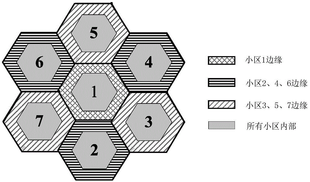
[0114] Assume Figure 6 The middle cell 1 is a reference cell. There are 3 sectors in the cell, 12 users in each sector, and 24 RBs (Resource Blocks) in the cell. Each RB contains 12 consecutive subcarriers in the frequency domain. The carrier width is 15kHz, and the RB frequency interval is 180kHz. That is, a time slot adopts video service, and the service data volume is 64kb / s. Assume that after user classification in a certain sector of the cell, there are 7 edge users and 5 central users.

[0115] Such as Figure 12 Shown are the effect diagrams of cells 1, 2, and 3 after initial allocation of frequency resources. For cell 1, if the resources in the figure do not identify user types, it means that the resources are idle and not occupied by users. For cells 2 and 3, part of the user type identifiers are omitted. Among them, the 1st to 8th RBs are the legal frequency ranges of edge users in cell 1; the 9th to 16th RBs are the legal frequency ranges of edge users in cell ...


PUM


Abstract

The invention discloses an LTE system interference coordination method, comprising: step 1, dividing users into center users and boundary users according to a CQI channel quality indicator report fed back by every user in every cell, wherein the boundary users are divided into legal users and default users, the default users are divided into hidden default users and obvious default users, the obvious default users are divided into absolute default users and non-absolute default users; step 2, carrying out frequency resource preliminary distribution to grouped users on all usable frequency bands of every cell according to a traditional PF proportional fairness scheduling algorithm; step 3, classifying the boundary users with preliminarily distributed frequency resources, making up the boundary users of every cell to obtain a list A and a list B; and step 4, carrying out frequency resource secondary adjustment to the cells, and finishing frequency resource distribution after adjustment.

Description

technical field [0001] The invention belongs to the field of wireless communication, and more specifically relates to an interference coordination method for an LTE (Long Term Evolution, long term evolution) system. Background technique [0002] 3GPP (Third Generation Partnership Project, Third Generation Partnership Project) standard organization launched 3G (the3G) as early as the end of 2004 rd Generation, the third generation) LTE and SAE (System Architecture Evolution, system architecture evolution) two major research and standardization work plans. After years of intense and efficient work, the LTE standard has matured. LTE improves and enhances the air interface technology of 3G, and introduces new wireless communication technologies such as OFDM (Orthogonal Frequency Division Multiplexing, Orthogonal Frequency Division Multiplexing), MIMO (Multiple Input, Multiple Output), and all-IP (Internet Protocol, Internet Protocol) networking. , so that the transmission capa...

Claims


Application Information

Patent Timeline
Patent Type & Authority Applications(China)
IPC IPC(8): H04W16/14H04W72/04H04B7/06H04B7/04
CPCH04W16/14H04B7/0452H04B7/0632H04W72/0453
Inventor 王斌刘圣洁李新朱晨鸣王强黄毅
Owner CHINA INFOMRAITON CONSULTING & DESIGNING INST CO LTD
Learn More