Supercharge Your Innovation With Domain-Expert AI Agents!

Pedal reactive force control device

A control device and pedal technology, which is applied in the layout of control devices, mechanical control devices, and power device control mechanisms, etc., can solve the problems of inability to transmit the operation amount of the accelerator pedal, insufficient visual information of the driver, etc.

Active Publication Date: 2016-05-04
HONDA MOTOR CO LTD
View PDF7 Cites 6 Cited by
  • Summary
  • Abstract
  • Description
  • Claims
  • Application Information

AI Technical Summary

Problems solved by technology

[0010] Although the driving operation assisting device described in Patent Document 1 can transmit the magnitude and change of the potential risk to the driver through stimulation (accelerator pedal reaction force) and visual information, it cannot convey to the driver the amount and potential risk of the accelerator pedal. Visual information on the relationship between the magnitude of the risk
Therefore, the driving operation assisting device described in Patent Document 1 may not provide enough visual information to the driver for assisting driving operations other than collision avoidance with obstacles.

Method used


Image

  • Pedal reactive force control device
  • Pedal reactive force control device
  • Pedal reactive force control device

Examples


Embodiment Construction

[0056] Hereinafter, embodiments of the present invention will be described in detail with reference to the drawings as appropriate.

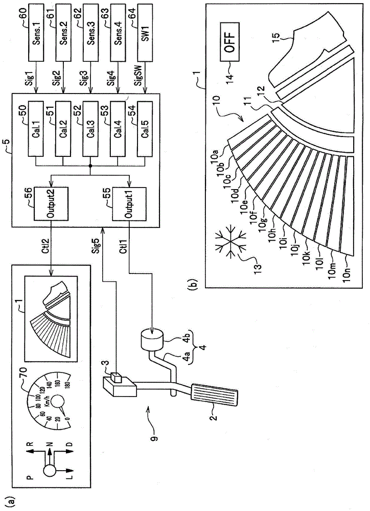
[0057] figure 1 (a) is a figure which shows the outline|summary of the pedal reaction force control apparatus of this embodiment, figure 1 (b) is a diagram showing a reaction force state display device included in the pedal device.

[0058] The pedal reaction force control device 9 of the present embodiment includes a reaction force state display device 1 , a pedal (accelerator pedal 2 ), and a stroke sensor 3 for detecting a depression operation amount of the accelerator pedal 2 (accelerator operation amount SL).

[0059] The accelerator pedal 2 is configured to automatically return to a predetermined reference position by an urging mechanism (return spring, etc.) not shown, and a predetermined reaction force (pedal reaction force Pp) is always applied by the urging mechanism.

[0060] In addition, the pedal reaction force control device 9 in...


PUM


Abstract

The purpose of the present invention is to provide a pedal reactive force control device including an information transmission means capable of transmitting visual information about the relationship between the amount of depressing operation of a pedal and a change in pedal reactive force to the driver. A pedal reactive force control device (9) includes: a reactive force generation device (4) that increases pedal reactive force (Pp) by adding additional reactive force (Pa) to an accelerator pedal (2); and a reactive force state display device (1) that converts the amount of depressing operation of the accelerator pedal (2) to visual information and that transmits the visual information to the driver by displaying the information on an operation amount display unit (10). The reactive force state display device (1) is characterized in that the visual information includes identification information enabling the driver to identify whether the additional reactive force (Pa) is being generated by the reactive force generation device (4).

Description

technical field [0001] The invention relates to a pedal reaction force control device of a vehicle. Background technique [0002] For example, Patent Document 1 describes a driving operation assisting device (pedal reaction force control device) that calculates the potential risk of the driver's driving and transmits the calculated value to the driver through the accelerator pedal reaction force (stimulus amount). potential risks, and also convey potential risks to the driver through visual information. [0003] The driving assistance device described in Patent Document 1 can notify the driver that the potential risk exceeds a predetermined maximum value through visual information (flickering of the preceding vehicle) displayed on a display monitor (see FIG. 34 ). Alternatively, the change in potential risk can be conveyed to the driver through visual information displayed in a graph (see FIG. 40 ). [0004] In this way, the driving operation assisting device described in ...

Claims


Application Information

Patent Timeline
IPC IPC(8): B60K35/00B60K26/04B60W10/00B60W20/00F02D11/10
CPCB60K26/04B60K35/00B60W10/00B60W20/00F02D11/10F02D2041/228B60K26/021B60K2026/023B60K2310/22Y10S903/93B60K35/20B60K2360/1515B60K35/28B60K2360/168B60K35/10B60K26/02G05G1/38
Inventor 须崎豪根布谷秀人千尚人佐藤好一丸山耕平洼田昌寿浜田次郎
Owner HONDA MOTOR CO LTD
Features
  • R&D
  • Intellectual Property
  • Life Sciences
  • Materials
  • Tech Scout
  • Unparalleled Data Quality
  • Higher Quality Content
  • 60% Fewer Hallucinations
Learn More