Apparatus and method for deploying an object to a sea floor

A technology of equipment and objects, which is applied in the field of equipment for deploying objects to the seabed, and can solve problems such as size restrictions

Inactive Publication Date: 2016-05-04
索尔机械动力有限公司
View PDF5 Cites 3 Cited by
  • Summary
  • Abstract
  • Description
  • Claims
  • Application Information

AI Technical Summary

Problems solved by technology

however, this configuration has the disadvantage that it only works effectively on flat or smooth seabed surfaces and is severely limited in the size of work vehicles that can be deployed from a surface vessel of a given size

Method used


Image

  • Apparatus and method for deploying an object to a sea floor
  • Apparatus and method for deploying an object to a sea floor
  • Apparatus and method for deploying an object to a sea floor

Examples


Embodiment Construction

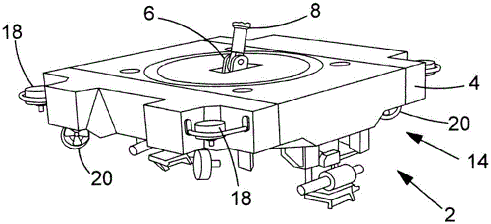
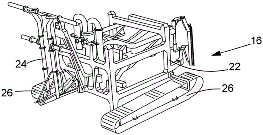
[0078] see figure 1 A known deployment device 2 forming part of a subsea remotely operated vehicle (ROV) has a body 4, a connection portion 14, and vertical thrusters 18 and horizontal thrusters 20 arranged at respective corners of said body 4, the The body 4 has a connection point 6 for a hoisting cable 8, and the connection portion 14 is used to make objects or equipment (such as spray vehicles 16 ( figure 2 )) can be releasably connected to the connecting portion 14, so that the instrument can be releasably connected to the deployment device 2, the vertical thruster 18 and the horizontal thruster 20 are used to move between the first site and the second site Move the device 2 between.

[0079] Figure 14 and Figure 15 A deployment device 2 is shown characterizing the invention. The deployment device 2 has a body 4 with a connection point 6 for a hoisting cable 8 ( Figure 15 ), said buoyancy elements are in the form of inflatable tanks 10, 12 rotatably connected to s...


PUM


Abstract

The invention provides an apparatus and method for deploying an object to a sea floor. A deployment apparatus (2) for deploying an object to a sea floor is disclosed. The deployment apparatus comprises a body (4) and an attachment part (14) mounted to the body for releasably attaching an object to the apparatus. Thrusters (18, 20) provide thrust to transport the apparatus having an object attached thereto, and inflatable tanks 10, 12) mounted to the body have adjustable buoyancy.

Description

technical field [0001] The present invention relates to an apparatus and method for deploying objects to the seafloor, and more particularly, but not exclusively, to an apparatus and method for deploying an instrument or structure from a ship through sea ice to the seafloor. Background technique [0002] It is known, for example in the Arctic, to pass sea ice deployment structures or implements to the seabed by attaching guide lines extending from holes in the deck of an icebreaker to the sea bed and then guiding the structure or implement into position along said guide lines . However, this arrangement has the disadvantage that the location of the structure or apparatus on the seabed can only be within a limited lateral distance of the seabed area directly below the ship. This in turn limits the range of applications in which the structure or instrument can be used. [0003] Patent document US3633530 discloses an underwater working vehicle having a pontoon that can be fil...

Claims


Application Information

Patent Timeline
Patent Type & Authority Applications(China)
IPC IPC(8): B63G8/00E02F9/00E21B41/04E21B15/02F16L1/16H02G1/10
CPCB63G8/001E21B41/04F16L1/16F16L1/168H02G1/10B63B2211/06B63G2008/002E21B41/0007E21B19/002E02F3/9225E02F5/109E21B15/02E02F9/003
Inventor 约翰·格雷姆·沃克
Owner 索尔机械动力有限公司
Why Eureka
Try Eureka