
An emission imaging device with a polyhedral cavity structure

An imaging device, a polyhedron technology, which is used in radiation detection devices, clinical applications of radiological diagnosis, instruments for radiological diagnosis, etc. The effect of increasing the axial distance and increasing the solid angle of space

Active Publication Date: 2018-06-12
HUAZHONG UNIV OF SCI & TECH
View PDF4 Cites 0 Cited by
  • Summary
  • Abstract
  • Description
  • Claims
  • Application Information

AI Technical Summary

Problems solved by technology

[0004] In view of the above defects or improvement needs of the prior art, the present invention provides an emission imaging device, in which the emission imaging device with a polyhedral cavity structure is obtained through the combination and cooperation of a plurality of polygonal modules. The upper part and the lower part are composed of the upper part and the lower part, wherein the lower part leaves a gap for the object to be detected to enter the polyhedron cavity, and the polygonal module in the lower part can move along the diameter of the lower support frame with the cooperation of the sliding device and the power mechanism. Expansion to meet the needs of different sizes of objects to be detected entering the detection area, and solve the problems of insufficient spatial resolution and sensitivity of the equipment caused by the excessive size of the existing equipment for local organ diagnosis and the small solid angle of the coverage space. It is suitable for the detection of local organs of the human body such as human brain imaging or small animals

Method used


Image

  • An emission imaging device with a polyhedral cavity structure
  • An emission imaging device with a polyhedral cavity structure
  • An emission imaging device with a polyhedral cavity structure

Examples


Embodiment 1

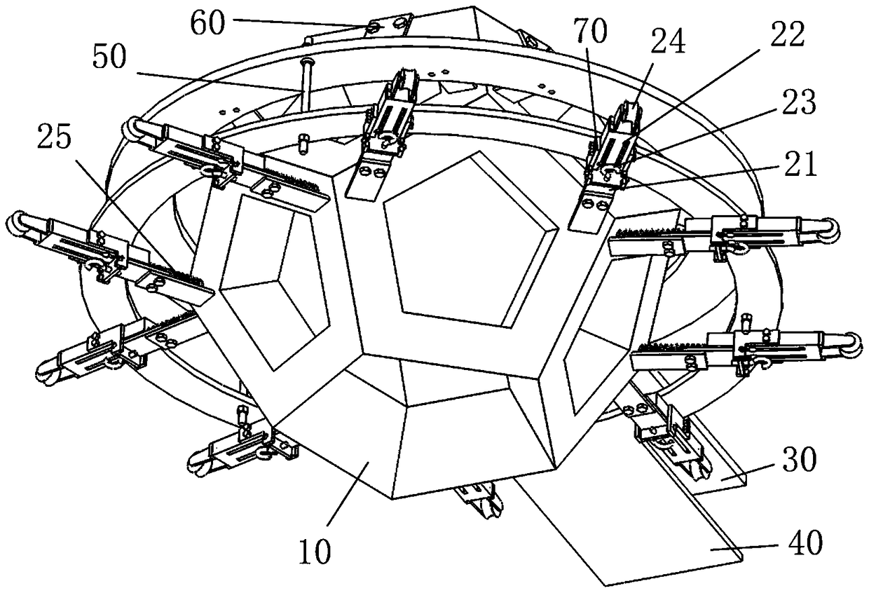
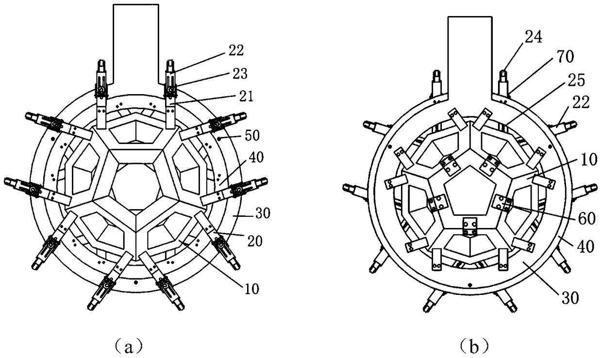
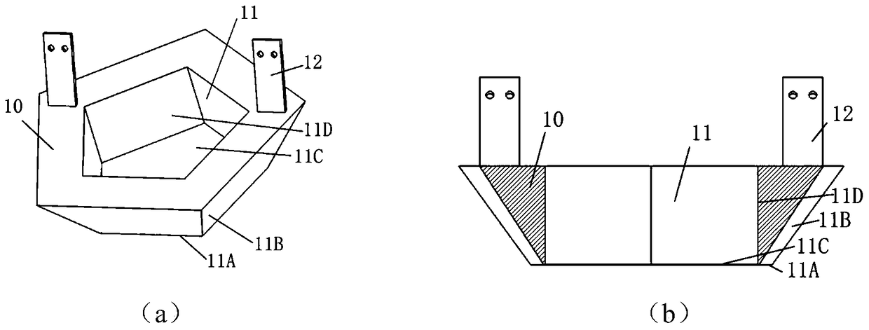
[0042] Such as figure 1 As shown, in this embodiment, the cavity structures 11 of the polygonal modules 10 are all regular pentagons, and detection elements such as crystal arrays and optical sensors are installed in the cavity structures 11, and the outer surfaces 11B of the eleven polygonal modules 10 are arranged in pairs. Splicing together to form a regular dodecahedron with a gap, forming a regular dodecahedron cavity;

[0043] There is a vacancy of a polygonal module 10 at the bottom of the dodecahedron structure, which is used to allow the detected object to enter the cavity of the dodecahedron. The polygonal modules 10 around the vacancy are installed on their own independent sliding systems 20, and then installed on the lower support frame 40, forming the lower half of the dodecahedron structure, the polygonal modules 10 adjacent to the lower half are directly installed on the upper support frame 30, and fixed with the remaining polygonal modules 10 through obtuse ang...

Embodiment 2

[0048] Such as Figure 9 As shown in (a) and (b), the structure and composition of the imaging device in this embodiment are basically the same as in Embodiment 1, the only difference is that the cavity structures 11 of the polygonal module 10 are not all regular pentagons, which include regular Pentagons and regular hexagons, twelve regular pentagons and nineteen regular hexagons together form a truncated icosahedron with a gap; the angle of the obtuse connecting block 60 is 138.19 ° or 142.623 °, with For connecting two hexagons and pentagons and hexagons.


PUM


Abstract

The invention discloses an emission imaging device with a polyhedral cavity structure. The emission imaging device comprises an upper supporting frame and an upper polyhedral cavity structure that are connected with each other, as well as a lower supporting frame and a lower polyhedral cavity structure that are connected with each other, wherein the upper supporting frame is connected with the lower supporting frame through a connecting rod; the upper polyhedral cavity structure is composed of polygonal modules of a plurality of cavity structures; the outer side surfaces of the polygonal modules are spliced in pairs in sequence to form a hollow polyhedral cavity structure; a hollow part of the polyhedral cavity structure is embedded with a polygonal module; the lower polyhedral cavity structure is also composed of the polygonal modules of the plurality of the cavity structures; each sliding apparatus comprises a sliding block and a guide rail; the sliding blocks are connected with the polygonal modules and slide relative to the guide rails under the driving action of a power mechanism; the guide rails are connected with the lower supporting frame; and springs are arranged between one ends of the guide rails and the polygonal modules or the sliding blocks. The emission imaging device has the advantages of simple structure, convenience and accuracy for detection, high detection resolution and the like, and is suitable for detection of local organs of a human body or small animals.

Description

technical field [0001] The invention belongs to the field of emission imaging systems, and more particularly relates to an emission imaging device with a polyhedron cavity structure. Background technique [0002] Emission imaging equipment has been widely used in scientific experiments and clinical medical diagnosis. Taking positron emission imaging equipment as an example, it uses the phenomenon that the positrons produced by the decay of positron isotopes and the negative electrons in the human body have an annihilation effect, leading to the human body. Inject the compound labeled with positron isotope, adopt the compound detection method, use the detector to detect the gamma photons generated by the annihilation effect, obtain the distribution information of the isotope in the human body, and reconstruct and combine the operation by the computer, so as to obtain the distribution of the labeled compound in the human body 3D tomographic images. [0003] However, the exist...

Claims


Application Information

Patent Timeline
Patent Type & Authority Patents(China)
IPC IPC(8): A61B6/00A61B6/03
CPCA61B6/037A61B6/42A61B6/44A61B6/50A61B6/501A61B6/508A61B2503/40
Inventor 许剑锋陈杰彭旗宇谢思维杨明明
Owner HUAZHONG UNIV OF SCI & TECH
Learn More