Tube grinding system

A grinding and pipe material technology, applied in the direction of grinding feed movement, grinding workpiece support, grinding machine tool parts, etc., can solve problems affecting product quality, inconvenient operation, uneven grinding, etc., to improve product quality , improve the efficiency of grinding, improve the effect of work efficiency

Inactive Publication Date: 2016-05-11
RONGCHANG YONGXIN STEEL STRUCTURE PROCESSING FACTORY
View PDF0 Cites 0 Cited by
  • Summary
  • Abstract
  • Description
  • Claims
  • Application Information

AI Technical Summary

Problems solved by technology

There are many disadvantages in this way, such as: the staff will be fatigued during product processing, which will affect the safety of production. Due to the manual clamping and placement, it is easy to cause personal injury. The existing feeding mechanism has a complex structure and is inconvenient to operate. Human factors affect the quality of products during product processing
And the current grinding head mechanism cannot move up and down, the use process is greatly restricted, and the applicability is low
At the same time, when the pipe is ground, the existing supporting mechanism is relatively complicated, and it is not easy to adjust the pipe, resulting in uneven grinding and affecting the quality of the product
And with the widespread use of steel pipes, there are more and more requirements for steel pipes, and in the processing and manufacturing of steel pipes, it is often necessary to measure the wall thickness of steel pipes to achieve accurate production and processing. The measuring device only measures the steel pipe at one angle during measurement, which causes many errors in the measurement of the steel pipe, and during the measurement process, due to the shaking and vibration of the steel pipe, the measurement has a large deviation, which affects the production quality of the steel pipe

Method used


Image

  • Tube grinding system
  • Tube grinding system
  • Tube grinding system

Examples


Embodiment Construction

[0037] Below in conjunction with accompanying drawing and embodiment the present invention will be further described:

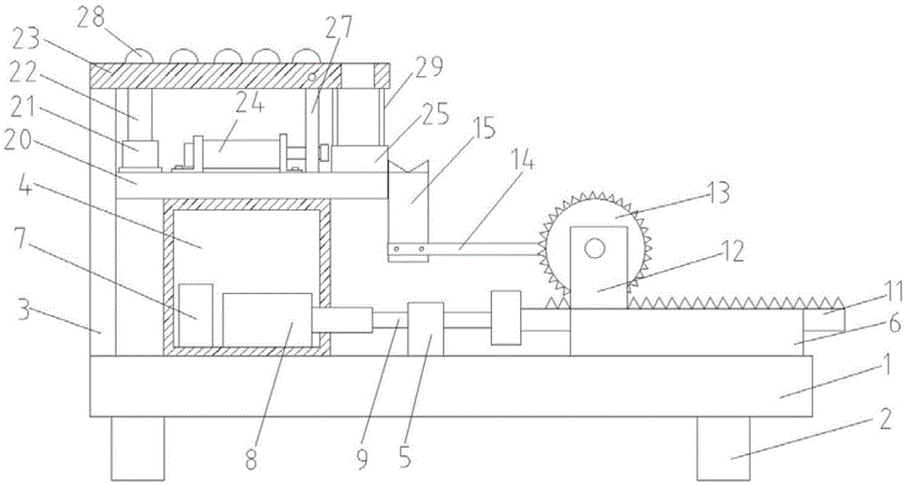
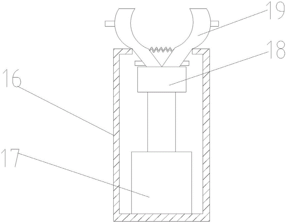
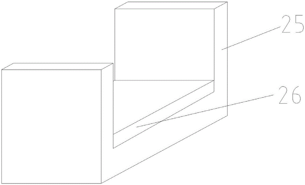
[0038] Such as figure 1 , figure 2 , image 3 , Figure 4 , Figure 5 , Figure 6 , Figure 7 , Figure 8 , Figure 9 , Figure 10 , Figure 11 and Figure 12 As shown, this embodiment includes a feeding device, a material holding device, a grinding device and a measuring device, the feeding device is located at the discharge end of the feeding device, the grinding device is located above the feeding device, and the measuring device The device is located at the discharge end of the grinding device.

[0039] The feeding device includes a machine base 1, the bottom of which is equipped with a support leg 2, and the upper surface of the machine base 1 is provided with a pillar 3, a working box 4, a support block 5 and a support seat 6 in sequence from left to right , the inner left side of the working box 4 is provided with a controller 7, the inner...


PUM


Abstract

The invention discloses a tube grinding system. The tube grinding system comprises a feeding device, a supporting device, a grinding device and a measuring device, wherein the supporting device is positioned at a discharging end of the feeding device; the grinding device is positioned above the supporting device; and the measuring device is positioned at a discharging end of the grinding device. Automatic feeding is realized through the feeding device, the supporting mechanism with an adjusting function is adopted, and is simple in structure and convenient to operate, an adjustable effect is achieved, through a lifting device, a whole grinding head mechanism can move in the up-down direction and the left-right direction, service restriction is avoided, after a steel tube is ground, a first clamping device is matched with a second clamping device, the steel tube can rotate when clamped, and then can be measured by the measuring device at various angles, vibrating and shaking of the steel tube are reduced, by a bearing plate, the steel tube can be placed stably and is measured accurately, errors are reduced, and the measurement effect of the steel tube is good.

Description

technical field [0001] In particular, the invention relates to a tube grinding system. Background technique [0002] Pipe is the material used to make pipe fittings. Different pipes use different pipes. The quality of pipes directly determines the quality of pipes. Pipes are necessary materials for construction projects. Commonly used are water supply pipes, drain pipes, gas pipes, and heating pipes. Tubes, wire conduits, rainwater pipes, etc., the cylindrical grinding of pipes is an important part of pipe machining. At present, the process of pipe processing is generally to manually move the pipe to the supporting mechanism of the grinding machine, and process it through the grinding device. There are many disadvantages in this way, such as: when the product is processed, the staff will be fatigued, which will affect the safety of production. Due to the manual clamping and placement, it is easy to cause personal injury. The existing feeding mechanism has a complex structur...

Claims


Application Information

Patent Timeline
Patent Type & Authority Applications(China)
IPC IPC(8): B24B41/00B24B41/06B24B49/00B24B5/04B24B55/00
CPCB24B41/005B24B5/04B24B41/06B24B49/00B24B55/00
Inventor 刘全
Owner RONGCHANG YONGXIN STEEL STRUCTURE PROCESSING FACTORY
Why Eureka
Try Eureka