a vertical walking track

A walking track and vertical technology, applied in the direction of manipulators, manufacturing tools, etc., can solve the problems that the straightness and flatness of the manipulator cannot be guaranteed, and achieve the effect of improving production and processing efficiency, improving processing efficiency, and expanding the working space

Active Publication Date: 2018-01-02
广东泰格威机器人科技有限公司
View PDF8 Cites 0 Cited by
  • Summary
  • Abstract
  • Description
  • Claims
  • Application Information

AI Technical Summary

Problems solved by technology

[0004] The purpose of the present invention is to overcome the shortcomings and deficiencies in the prior art, and to provide a vertical walking track, which can effectively solve the problem that the straightness and straightness of the mechanical arm walking motion cannot be guaranteed due to uneven ground, thereby Improve the quality of the manipulator clamping the profile for processing; at the same time, the walking track can reduce the floor space occupied by the manipulator movement

Method used


Image

  • a vertical walking track
  • a vertical walking track

Examples


Embodiment 1

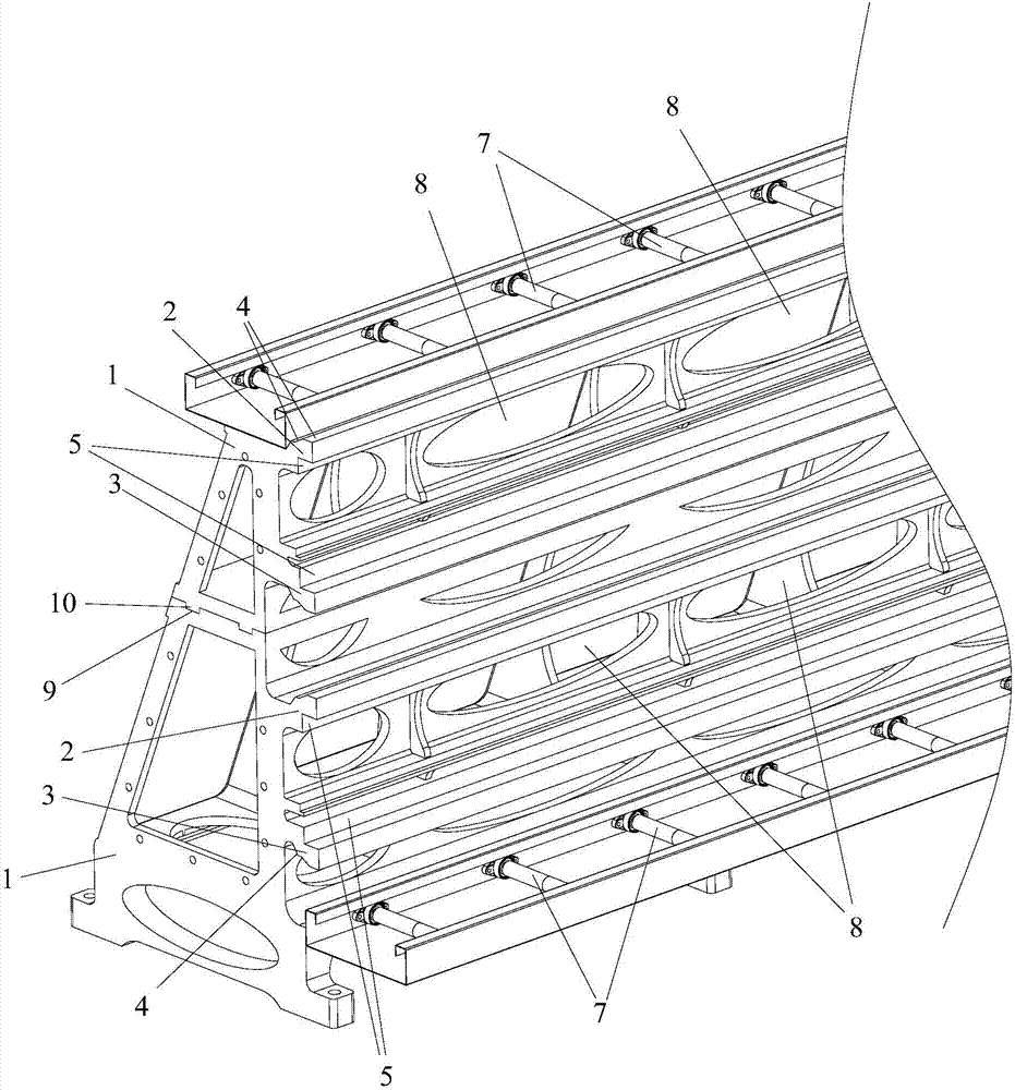
[0026] In this embodiment, the track main frame formed by superimposing two vertical walking tracks is taken as an example to describe the following.

[0027] Such as figure 1 and figure 2 As shown, the track assembly frame of the present invention is composed of two vertical walking tracks superimposed, and the groove 9 arranged at the top of the lower walking track and the convex strip arranged at the bottom of the upper walking track are passed between the two vertical walking tracks. 10 achieve superimposition, while groove 9 and ridge 10 match.

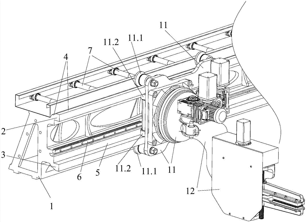
[0028] Each vertical walking track of the track assembly frame is used to slide and connect with the vertical walking mechanism 11 to realize the walking movement of the mechanical arm 12. The vertical walking track includes a frame body 1, and the side of the frame body 1 is provided with The slide rail is used for buckling and sliding connection with the running mechanism 11, so that the running mechanism 11 is suspended on ...

Embodiment 2

[0033] Each vertical walking track in the track assembly frame of the present invention can be used independently, and each vertical walking track can be used for sliding connection with the vertical walking mechanism to realize the walking movement of the mechanical arm. When only one mechanical arm is needed for motion processing, any vertical walking track can be used to realize the walking mechanism hanging on the side of the frame for walking and moving.

[0034] The structure of each vertical walking track in the present embodiment is consistent with the structure of implementing a neutral vertical walking track.

[0035] Implementation three

[0036]The only difference between this embodiment and Embodiment 1 is that this embodiment can form the main frame of the track by superimposing three or more vertical walking tracks, and the structure of each vertical walking track is neutral to that of Embodiment 1. The structure of the walking track is the same.


PUM


Abstract

The invention provides a vertical walking rail for slidingly connecting with a vertical walking mechanism to realize walking movement of a mechanical arm. The vertical walking rail comprises a frame; and a slide rail is arranged on the side surface of the frame in the length direction, and is used for buckling and slidingly connecting with a walking mechanism to realize walking movement of the walking mechanism by hanging on the side surface of the frame. The vertical walking rail can effectively solve the problem of incapability of guaranteeing walking movement straightness of the mechanical arm caused by uneven ground so as to improve the quality of the clamping arm clamping a profile for machining. Meanwhile, the vertical walking rail can reduce the movement floor space of the mechanical arm. The invention further provides a rail assembly; the rail assembly is formed by superposing more than two vertical walking rails; and two adjacent vertical walking rails realize superposition through a superposing part 1 arranged at the top of the lower walking rail and a superposing part 2 arranged at the bottom of the upper walking rail. The rail assembly is convenient for movement machining of multiple mechanical arms so as to improve the machining efficiency.

Description

technical field [0001] The invention relates to the technical field of metal processing, and more specifically relates to a vertical walking track. Background technique [0002] The robotic arm is often used in the process of object handling and can replace manpower to work. In an environment that is unfavorable to the human body, it can replace people to work and maintain personal safety. The mechanical arm is mainly composed of three parts: the actuator, the driving mechanism and the control mechanism. The arm is used to grasp the workpiece. It adopts various structural forms according to the shape, size, weight and material of the grasped piece. Such as adsorption type, holding type and clamping type and so on. [0003] Usually, the manipulator needs to use the walking track as its flexible moving and walking track during the processing process, which greatly expands the working space of the manipulator. And the walking track of existing mechanical arm mostly adopts the...

Claims


Application Information

Patent Timeline
Patent Type & Authority Patents(China)
IPC IPC(8): B25J5/02
CPCB25J5/02
Inventor 卢新建廖子剑唐崇斌
Owner 广东泰格威机器人科技有限公司
Why Eureka
Try Eureka