Supercharge Your Innovation With Domain-Expert AI Agents!

Rope winding device and method for steel wire rope of crane

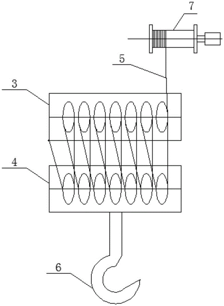
A technology for steel wire ropes and cranes, which is applied in the field of crane wire rope winding devices, which can solve the problems of limited and limited lifting height or descending depth, and affect the lifting weight, and achieve the effects of increasing length, reducing resistance, and speeding up lifting speed

Inactive Publication Date: 2016-05-11
重庆公路运输(集团)有限公司大件分公司
View PDF5 Cites 9 Cited by
  • Summary
  • Abstract
  • Description
  • Claims
  • Application Information

AI Technical Summary

Problems solved by technology

[0002] With the rapid development of my country's large-scale infrastructure construction, energy industry, real estate industry, petrochemical industry and shipbuilding industry in recent years, it has greatly promoted the development of my country's crane and other heavy machinery manufacturing industries. Existing cranes generally include a lifting Drum device, a fixed pulley block, a movable pulley block, steel wire rope and the hook fixed on the lower part of the movable pulley block, the steel wire rope wound on the lifting drum goes around the fixed pulley block and the fixed pulley block in turn, and finally the steel wire rope The winding end of the crane is fixed on the shelf of the fixed pulley block, and the motor or hydraulic motor drives the lifting drum to rotate, and the wire rope is retracted or lowered to realize the lifting function, but the current crane generally adopts the single lifting drum method When working, due to the limited rope length of a single lifting drum, the lifting height or descending depth is limited during application, and because the rope winding length of a single lifting drum is limited, the rope winding ratio is also limited, which affects the lifting effect. weight

Method used


Image

  • Rope winding device and method for steel wire rope of crane
  • Rope winding device and method for steel wire rope of crane
  • Rope winding device and method for steel wire rope of crane

Examples


Embodiment Construction

[0032] The technical solutions of the present invention will be clearly and completely described below in conjunction with the accompanying drawings. Apparently, the described embodiments are some of the embodiments of the present invention, but not all of them. Based on the embodiments of the present invention, all other embodiments obtained by persons of ordinary skill in the art without making creative efforts belong to the protection scope of the present invention.

[0033] In the description of the present invention, it should be noted that the terms "center", "upper", "lower", "left", "right", "vertical", "horizontal", "inner", "outer" etc. The indicated orientation or positional relationship is based on the orientation or positional relationship shown in the drawings, and is only for the convenience of describing the present invention and simplifying the description, rather than indicating or implying that the referred device or element must have a specific orientation, ...


PUM


Abstract

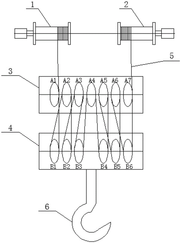
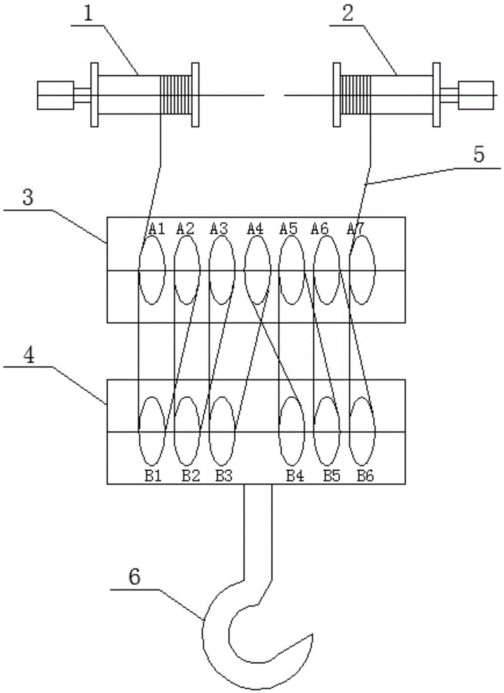
The invention provides a rope winding device and method for a steel wire rope of a crane. The rope winding device comprises a first hoisting winding drum device, a second hoisting winding drum device, a fixed pulley block, a movable pulley block, the steel wire rope and a lifting hook, and the lifting hook is fixedly installed on the lower portion of the movable pulley block. The steel wire rope is wound through the fixed pulley block, the movable pulley block, the second hoisting winding drum device and the first hoisting winding drum device in sequence. The first hoisting winding drum device and the second hoisting winding drum device are synchronously rotated so that the movable pulley block and the lifting hook can rise and fall. According to the rope winding device and method for the steel wire rope of the crane, the penetrating mode that the steel wire rope is wound through the two hoisting winding drum devices together to drive the fixed pulley block and the movable pulley block is adopted, the length of the wound steel wire rope is effectively increased, the problem that the length of a wound steel wire rope of a single hoister is limited is solved, and thus the purposes of increasing the rope winding multiple ratio of the crane, the hoisting height or the descending depth of the crane and the operating speed of the crane can be achieved.

Description

technical field [0001] The invention relates to the technical field of lifting equipment, in particular to a rope winding device and a rope winding method for a crane steel wire rope. Background technique [0002] With the rapid development of my country's large-scale infrastructure construction, energy industry, real estate industry, petrochemical industry and shipbuilding industry in recent years, it has greatly promoted the development of my country's crane and other heavy machinery manufacturing industries. Existing cranes generally include a lifting Drum device, a fixed pulley block, a movable pulley block, steel wire rope and the hook fixed on the lower part of the movable pulley block, the steel wire rope wound on the lifting drum goes around the fixed pulley block and the fixed pulley block in turn, and finally the steel wire rope The winding end of the crane is fixed on the shelf of the fixed pulley block, and the motor or hydraulic motor drives the lifting drum to ro...

Claims


Application Information

Patent Timeline
IPC IPC(8): B66D1/26B66D1/28
CPCB66D1/26B66D1/28
Inventor 陈志强梁华卯余国江杨春生邹小飞
Owner 重庆公路运输(集团)有限公司大件分公司
Features
  • R&D
  • Intellectual Property
  • Life Sciences
  • Materials
  • Tech Scout
  • Unparalleled Data Quality
  • Higher Quality Content
  • 60% Fewer Hallucinations
Learn More