Multi-point hoisting force balance device

An equalizing device and hoisting technology, which is applied in the direction of hoisting device, portable lifting device, etc., can solve the problems such as the inability to guarantee the complete force equalization of multiple points, the high cost of the electronic control system, the control accuracy and the cost can not fully meet the use requirements, etc. Achieve the effect of reducing equipment procurement and post-maintenance investment, obvious social and economic benefits, and no control errors

Active Publication Date: 2018-05-22
CHINA RAILWAY MAJOR BRIDGE ENG GRP CO LTD
View PDF5 Cites 0 Cited by
  • Summary
  • Abstract
  • Description
  • Claims
  • Application Information

AI Technical Summary

Problems solved by technology

The disadvantage is that the cost of the electronic control system is relatively high, and it can only be adjusted after the unbalanced multi-point force occurs. There is a certain control error, and the complete balance of multi-point force cannot be guaranteed.
[0005] Therefore, the above two balanced control systems cannot fully meet the requirements of use in terms of control accuracy and cost.

Method used


Image

  • Multi-point hoisting force balance device
  • Multi-point hoisting force balance device
  • Multi-point hoisting force balance device

Examples


Embodiment 1

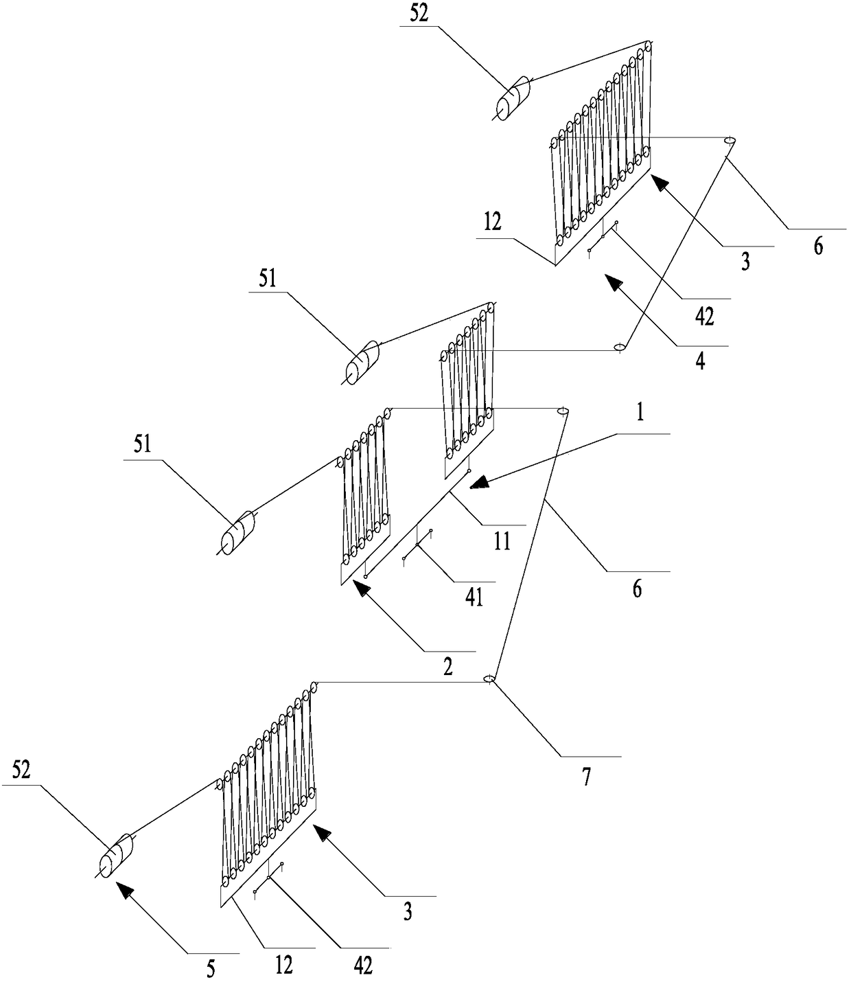
[0031] see figure 1 As shown, in this embodiment, a side truss lifting point 42 is provided on both sides of the center truss lifting point 41, the center truss lifting point 41 is connected with the center truss balance beam 11, and a center truss is provided at both ends of the center truss balance beam 11. Pulley block 2, each middle truss pulley block 2 is provided with 6 movable pulleys. A side truss balance beam 12 is provided on both sides of the center truss balance beam 11, and each side truss balance beam 12 is provided with a side truss pulley block 3, and each side truss pulley block 3 is provided with 12 movable pulleys, so that the center truss balance The number of movable pulleys connected to beam 11 and the quantity of movable pulleys connected to each side truss balance beam 12 are 12.

[0032] When lifting heavy objects, only two wire ropes are used to lift them. The wire ropes on each side of the balance beam 1 are guided through the adjacent center girde...

Embodiment 2

[0035] see figure 2 As shown, according to the need, when the size of the heavy object is small, the number of movable pulleys can be appropriately reduced. In this embodiment, a side truss lifting point 42 is respectively provided on both sides of the middle truss lifting point 41, and the middle truss lifting point 41 is connected with the middle truss balance beam 11, and a middle truss pulley block 2 is respectively provided at both ends of the middle truss balance beam 11, Each mid-truss pulley block 2 is provided with a movable pulley. A side truss balance beam 12 is provided on both sides of the center truss balance beam 11, and each side truss balance beam 12 is provided with a side truss pulley block 3, and each side truss pulley block 3 is provided with 2 movable pulleys, so that the center truss balance The number of movable pulleys connected to beam 11 and the quantity of movable pulleys connected to each side truss balance beam 12 are 2.

[0036] In the same way,...

Embodiment 3

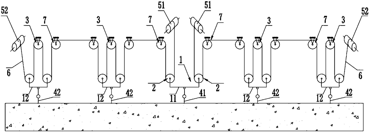
[0038] see image 3 As shown, if the load is heavy, the number of lifting points can also be appropriately increased. In this embodiment, there are two side truss lifting points 42 on both sides of the center truss lifting point 41. Correspondingly, two side truss balancing beams 12 are respectively arranged on both sides of the center truss balance beam 11, and each side truss lifting point 42 corresponds to a side girder balance beam 12, and each side girder balance beam 12 is provided with a side girder pulley block 3. Simultaneously, between the center truss pulleys 2 and the side truss pulleys 3 on one side of the center truss lifting point 41 and between the two side truss pulleys 3, a diverting pulley 7 is arranged.

[0039] The middle truss lifting point 41 is connected with the middle truss balance beam 11, and each of the two ends of the middle truss balance beam 11 is provided with a middle truss pulley block 2, and each middle truss pulley block 2 is provided with...


PUM


Abstract

The invention discloses a multipoint hoisting stress equalizing device and relates to the field of bridge hoisting. The multipoint hoisting stress equalizing device comprises an equalizing mechanism, a hoisting point device and a winch set. The equalizing mechanism comprises a middle girder equalizing beam and side girder equalizing beams located at the two sides of the middle girder equalizing beam. The two ends of the middle girder equalizing beam are provided with middle girder pulley blocks. Movable pulleys of the middle girder pulley blocks are connected with the middle girder equalizing beam. The side girder equalizing beams are provided with side girder pulley blocks. Movable pulleys of the side girder pulley blocks are connected with the corresponding side girder equalizing beams. The number of the movable pulleys connected with the middle girder equalizing beam is equal to the number of the movable pulleys connected with each side girder equalizing beam. The hoisting point device comprises a middle girder hoisting point and side girder hoisting points located at the two sides of the middle girder hoisting point. The middle girder hoisting point is connected with the middle girder equalizing beam. The side girder hoisting points are connected with the corresponding side girder equalizing beams. The winch set comprises first winches and second winches. The corresponding first winch, the middle girder pulley block and the side girder pulley block located at one side of the middle girder hoisting point, and the corresponding second winch are connected through a rope in sequence. The multipoint hoisting stress equalizing device is simple in structure, low in cost and capable of ensuring complete uniformity of multipoint stress.

Description

technical field [0001] The invention relates to the field of bridge hoisting, in particular to a multi-point hoisting force equalization device. Background technique [0002] In bridge construction, it involves the hoisting of some super-long, overweight and oversized parts. Two-point hoisting cannot meet the requirements, and multi-point hoisting must be used. At this time, the problem of multi-point hoisting force balance is involved. Traditionally used multi-point hoisting automatic equalization systems usually have the following two types: [0003] (1) Hydraulic lifting automatic balancing system. A set of hydraulic lifting devices are installed above the lifting points of heavy objects, equipped with a complex hydraulic control system to ensure that the oil pressure and stroke of multiple hydraulic devices are equal, and indirectly ensure the automatic balance of multi-point force. The advantage of this method is that it has a high degree of automation, a high degree ...

Claims


Application Information

Patent Timeline
Patent Type & Authority Patents(China)
IPC IPC(8): B66D3/06
CPCB66D3/06
Inventor 朱佳绪庞凤起杨荣南潘东发郑席晖许颖强林明伟甘一鸣
Owner CHINA RAILWAY MAJOR BRIDGE ENG GRP CO LTD
Why Eureka
Try Eureka