Car, resonant cavity and manufacturing method of resonant cavity

A manufacturing method and resonant cavity technology, which are applied to intake mufflers, engine components, machines/engines, etc., can solve the problems of low production efficiency and low yield, and achieve the solution of low yield, improve yield, and improve production. The effect of efficiency

Inactive Publication Date: 2016-05-11
力帆科技(集团)股份有限公司
View PDF6 Cites 0 Cited by
  • Summary
  • Abstract
  • Description
  • Claims
  • Application Information

AI Technical Summary

Problems solved by technology

[0003] At present, the resonant cavity on the market is made by one-piece molding, that is, the resonant cavity is di

Method used


Image

  • Car, resonant cavity and manufacturing method of resonant cavity

Examples


Embodiment Construction

[0021] In order to make the purpose, technical solutions and advantages of the embodiments of the present invention clearer, the technical solutions in the embodiments of the present invention will be clearly and completely described below in conjunction with the drawings in the embodiments of the present invention. Obviously, the described embodiments It is a part of embodiments of the present invention, but not all embodiments. Based on the embodiments of the present invention, all other embodiments obtained by persons of ordinary skill in the art without making creative efforts belong to the protection scope of the present invention.

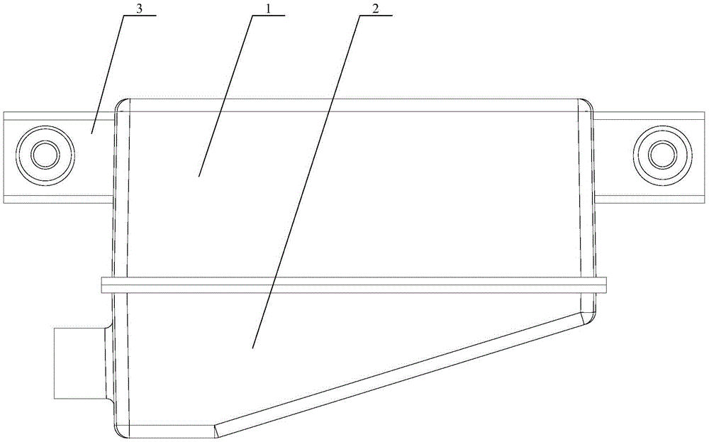
[0022] Please refer to figure 1 , figure 1 A schematic structural diagram of a resonant cavity provided by an embodiment of the present invention.

[0023] The resonant cavity provided by the embodiment of the present invention includes a housing, the housing is provided with an air inlet, the inside of the housing is a resonant cavity, the...


PUM


Abstract

The invention discloses a resonant cavity. The resonant cavity comprises a shell, the shell is provided with an air inlet, a resonant cavity body is formed in the shell, and the air inlet is communicated with the resonant cavity body; the shell comprises an upper shell body and a lower shell body, the upper shell body and the lower shell body are buckled for forming the shell, the upper shell body is provided with a first cavity, the lower shell body is provided with a second cavity, and the first cavity and the second cavity form the resonant cavity body when the upper shell body and the lower shell body are buckled. By dividing the resonant cavity body into the split structure of the upper shell body and the lower shell body, the production efficiency and the yield of the resonant cavity can be improved through the split optimization design compared with the original integrated structure of existing products, the problem that the original yield is low can be solved, and the production efficiency and the yield can be improved. The invention further discloses a car comprising the resonant cavity and a manufacturing method of the resonant cavity.

Description

technical field [0001] The invention relates to the technical field of automobile resonance, in particular to an automobile, a resonant cavity and a manufacturing method of the resonant cavity. Background technique [0002] The resonant cavity is installed, connected and fixed to the front wall of the body sheet metal. The air inlet introduces air into the resonant cavity from the drainage pipe. The resonant cavity acts as an intake muffler to eliminate low-frequency noise of the intake system. [0003] At present, the resonant cavity on the market is produced by one-piece molding, that is, the resonant cavity is directly produced through a blow molding process, but this one-piece molding production method has low yield and low production efficiency. [0004] Therefore, how to provide a resonant cavity to improve production efficiency is a technical problem to be solved urgently by those skilled in the art. Contents of the invention [0005] In view of this, the object of...

Claims


Application Information

Patent Timeline
IPC IPC(8): F02M35/12
CPCF02M35/1255F02M35/1283
Inventor 杨鑫
Owner 力帆科技(集团)股份有限公司
Why Eureka
Try Eureka