Tap water separator lifting hole machining equipment and water separator lifting hole machining method

A water separator and hole processing technology, applied in the field of valve parts processing, can solve the problems of low production efficiency, complex process, copper scraps and other problems, and achieve the effect of improving production efficiency and yield rate

Pending Publication Date: 2018-06-01
ZHEJIANG GAOAO SANITARY WARE CO LTD
0 Cites 0 Cited by

AI-Extracted Technical Summary

Problems solved by technology

[0002] There is a cylindrical lifting hole in the middle of the faucet diverter. The diverter is usually cut into small sections with a hollow copper tube according to the size. The height of each segment corresponds to the height of the diverter. The copper tube is usually made of molten method, the inner hole is smaller than the ...

Abstract

The invention provides tap water separator lifting hole machining equipment and a water separator lifting hole machining method, and belongs to the technical field of valve part machining. The equipment comprises a stand, and a pressing table arranged on the stand; the pressing table is provided with a press with an output shaft capable of axially reciprocating, and is detachably provided with a water separator fixed frame; an output shaft of the press is connected with a cylindrical pressing rod; and the position of the pressing rod is corresponding to the water separator fixed frame. The equipment gets rid of milling and polishing procedures needed by a traditional machining process, adopts once pressing molding to obtain qualified lifting holes, saves the polishing process, generates noruins, and synchronously improves the production efficiency and the yield.

Technology Topic

Image

  • Tap water separator lifting hole machining equipment and water separator lifting hole machining method
  • Tap water separator lifting hole machining equipment and water separator lifting hole machining method
  • Tap water separator lifting hole machining equipment and water separator lifting hole machining method

Examples

  • Experimental program(2)

Example Embodiment

[0022] Example 1
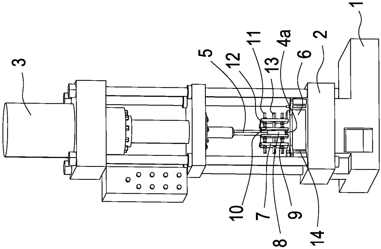
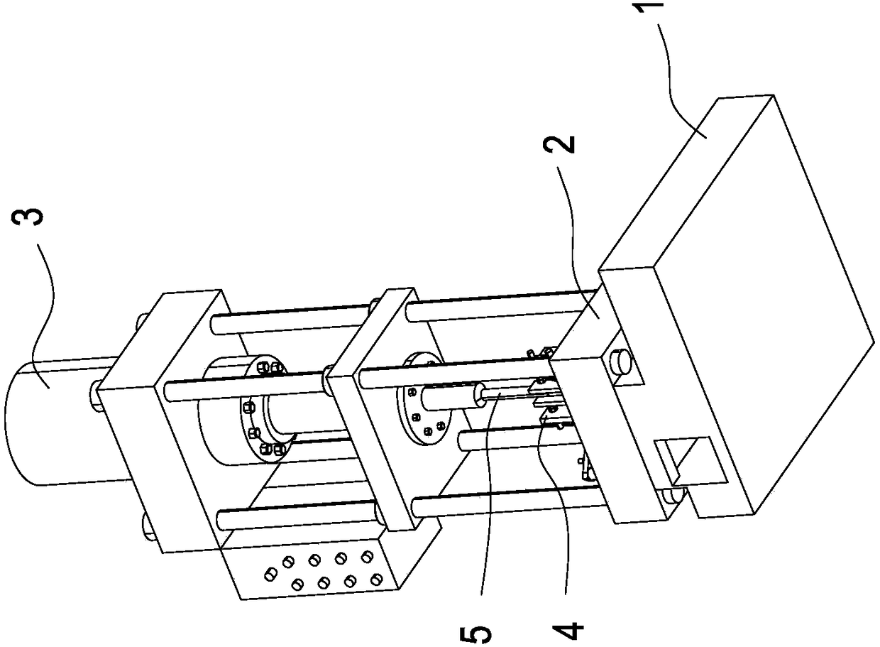
[0023] Such as Figure 1-3 As shown, a faucet splitter lifting hole processing equipment includes a machine base 1, and a material pressing table 2 arranged on the machine base 1, and the material pressing table 2 is provided with a device capable of reciprocating along the axial direction. The pressing table 2 of the output shaft compactor 3 is detachably provided with a water separator fixing frame 4, and the output shaft of the compactor 3 is connected with a cylindrical pressing rod 5 , The position of the pressing rod 5 corresponds to the water trap holder 4, and it also includes a steel ball. The diameter of the steel ball is larger than the diameter of the pulling hole of the water trap by 2-6 wires. The water trap holder 4 is provided with There is a blanking hole 4a, and the hole diameter of the blanking hole 4a is not less than the diameter of the steel ball. The compressor 3 is an air cylinder or an oil cylinder.
[0024] When the present invention is in use, put the water divider into the water divider fixing frame 4, put a steel ball on the top of the cylindrical lifting hole of the water divider, start the compactor 3, and the pressing rod 5 is aligned with the steel ball And drive the steel ball to press the steel ball into the lifting hole of the water separator, and expand the lifting hole of the water separator by 2-6 wires. Because the steel ball is spherical, the inner wall of the lifting hole of the water separator is ground during the process of expanding the hole. Light, without the polishing process, the steel ball enters the blanking hole 4a after leaving the pulling hole of the water separator.
[0025] The water separator fixing frame 4 includes a fixing seat 6 that is pressed on the pressing table 2, and the blanking hole 4a is located on the fixing seat. The fixing seat 6 is provided with a fixing frame 7, and the fixing frame 7 has a The size of the device is matched with the fixed groove 8, and the water separator is vertically placed in the fixed groove 8, and the fixed groove 8 is located directly under the pressing rod 5.
[0026] Two adjusting components 9 arranged parallel to each other are movably connected to the fixing frame 7, and a fixing slot 8 is formed between the two adjusting components 9.
[0027] The adjusting assembly 9 includes an adjusting plate 10 detachably connected to the fixing frame 7, two adjusting plates 10 on the two adjusting assemblies 9 are arranged in parallel with each other, and a fixing slot 8 is formed between the two adjusting plates 10.
[0028] At least one positioning rod 11 is provided on the adjusting plate 10. One end of the positioning rod 11 is fixedly connected with the adjusting plate 10, and the other end penetrates into the fixing frame 7 to be movably connected to the fixing frame 7. The positioning rod 11 is provided with two positioning rods. Two compression nuts 12 are located on both sides of the fixing frame 7.
[0029] A guide rod 13 is also fixed on the adjustment plate 10. The guide rod 13 penetrates into the fixing frame 7 and is movably connected to the fixing frame 7. The bottom of the adjustment plate 10 is pressed on the fixing seat 6.
[0030] There are two positioning rods 11, and the two positioning rods 11 are located on both sides of the guide rod 13.
[0031] The fixing base 6 is pressed on the material pressing table 2, and a plurality of pressing components 14 capable of pressing the top of the fixing base 6 are provided on the material pressing table 2.
[0032] The fixing seat 6 is in the shape of a cubic column, and the pressing table 2 is provided with four pressing components 14 corresponding to one corner of the fixing seat 6 respectively.
[0033] The pressing assembly 14 includes a material pressing positioning column 15 fixed on the material pressing table 2 and having the same height as the fixing seat 6, and a material pressing positioning screw 16 fixed on the material pressing table 2, and the material pressing plate 17 is sleeved on the material pressing In the positioning screw 16, the two ends of the pressing plate 17 are respectively pressed on the fixing seat 6 and the pressing positioning column 15. The pressing positioning screw 16 is screwed with a pressing nut 18 and the pressing nut 18 is located on the pressing Above the board 17.
[0034] The working principle of the present invention is:
[0035] Place the holder 4 of the water separator on the pressing table 2, adjust the position so that the fixing groove 8 is aimed below the pressing rod 5, and press the fixing seat 6 with the pressing plate 17 and the pressing nut 18, and the water separator is placed vertically. Into the fixed groove 8, put a steel ball on the top of the lifting hole of the water separator, start the compressor 3, and the pressing rod 5 will press the steel ball into the lifting hole of the water separator and move all the way down. The bottom of the water separator is pressed out and enters the blanking hole 4a, the internal lifting hole of the water separator is polished, and the diameter of the lifting hole is changed to the set standard.
[0036] Those skilled in the art should understand that the diameter of the steel ball is the diameter of the final lifting hole.

Example Embodiment

[0037] Example 2
[0038] This embodiment adopts the equipment of embodiment 1 to provide a method for processing the lifting hole of the faucet separator. Specifically, the water separator is placed in the water separator fixing frame (4), on the top of the water separator Put a steel ball whose diameter is 2-6 wires larger than the inner diameter of the inner hole of the water separator, start the compactor (3) so that the pressing rod (5) pushes the steel ball into the inner hole of the water separator and finally Pass through the inner hole of the water separator.
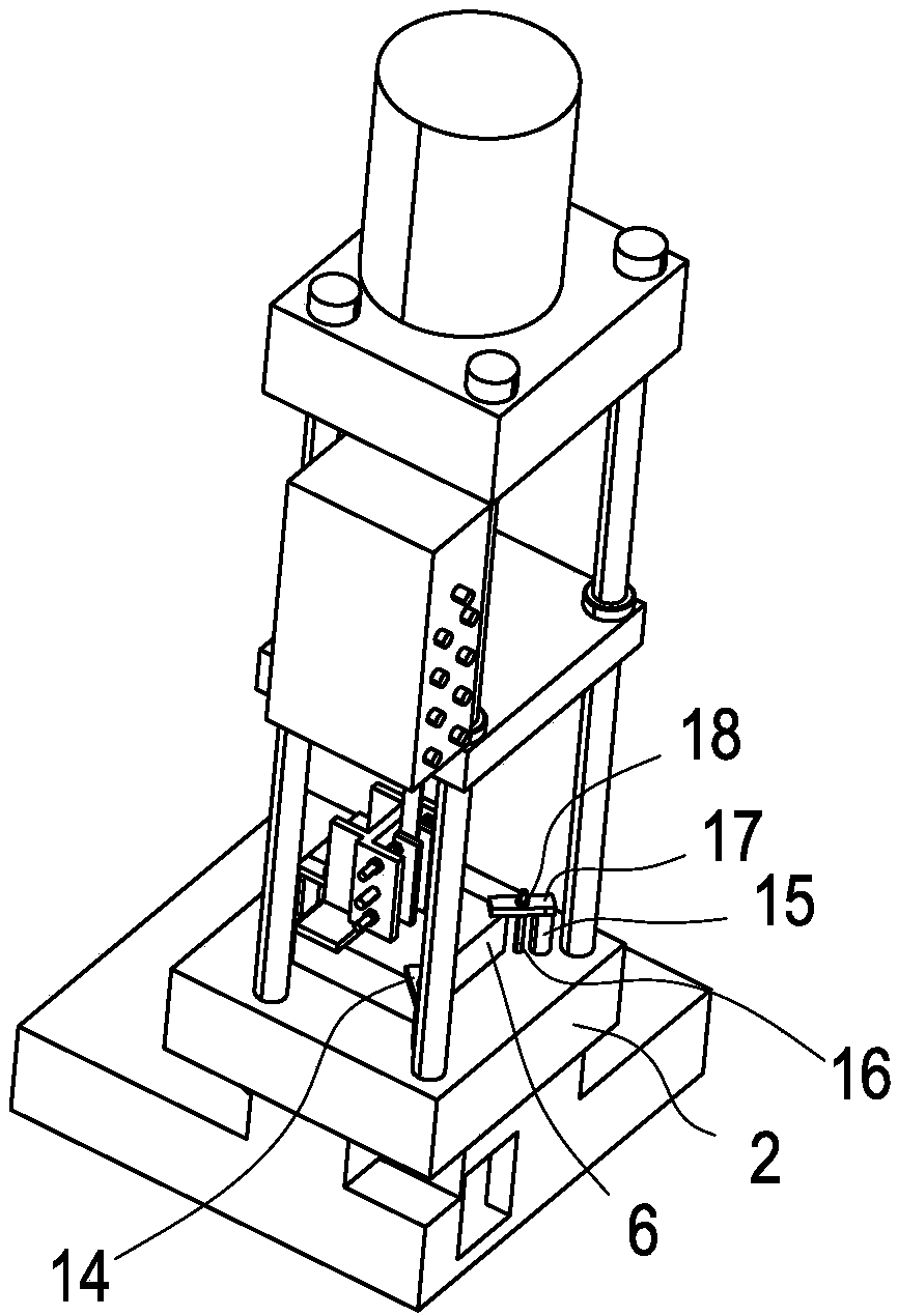
[0039] More specifically, a steel ball whose diameter is the diameter of the processed water separator lifting hole is selected, the water separator holder 4 is placed on the pressing table 2, and the position is adjusted so that the fixing groove 8 is directed below the pressing rod 5. The material plate 17 cooperates with the pressing nut 18 to compress the fixing seat 6, the water separator is placed in the fixing groove 8 vertically, and a steel ball is placed on the top of the lifting hole of the water separator, and the compressor 3 is activated to press the material The rod 5 presses the steel ball into the lifting hole of the water separator and moves all the way down, and finally presses out from the bottom of the water separator and enters the blanking hole 4a. The lifting hole inside the water separator is polished and the lifting is changed. The hole diameter is up to the set standard.

PUM

no PUM

Description & Claims & Application Information

We can also present the details of the Description, Claims and Application information to help users get a comprehensive understanding of the technical details of the patent, such as background art, summary of invention, brief description of drawings, description of embodiments, and other original content. On the other hand, users can also determine the specific scope of protection of the technology through the list of claims; as well as understand the changes in the life cycle of the technology with the presentation of the patent timeline. Login to view more.

Similar technology patents

Oil-based titanium-steel anti-bonding paint and application thereof

ActiveCN106221498AImprove product precision size and surface qualityImprove production efficiency and yieldFireproof paintsEpoxy resin coatingsTitaniumDimensional precision
Owner:PANGANG GROUP RESEARCH INSTITUTE CO LTD

Classification and recommendation of technical efficacy words

Why Eureka
Try Eureka