

Position guiding compaction device for rolling mill
A technology of pressing device and guiding position, which is applied in the direction of guiding/positioning/aligning device, etc., can solve the problems of alloy plate being easily twisted and broken, and achieve the elimination of torsion and tension, saving production cost, improving production efficiency and product quality rate effect
- Summary
- Abstract
- Description
- Claims
- Application Information
AI Technical Summary
Problems solved by technology
Method used
Image

Examples
Embodiment Construction
[0011] In the following, the milling machine cutting machine of the prior art and the embodiment of the present invention will be analyzed in conjunction with the accompanying drawings, and the specific implementation of the present invention will be further described in detail, so as to make the technical solution of the present invention easier to understand and grasp.
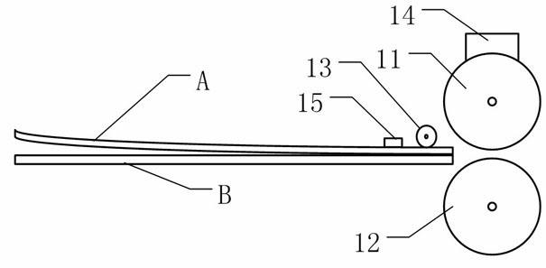
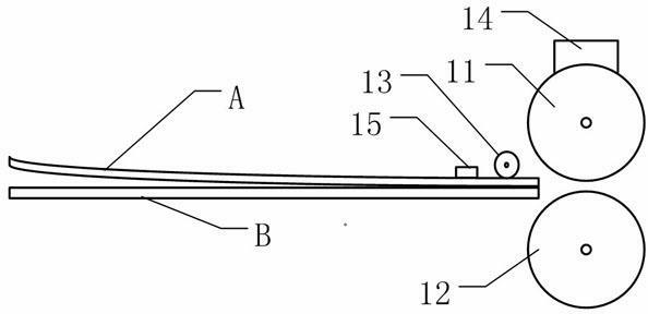
[0012] Such as figure 1 The schematic diagram of the overall structure of the rolling mill is shown. The rolling mill has an upper pressing roll 11 and a lower pressing roll 12 for compounding two metal sheets. As shown in the figure), and the upper pressing roller 11 is equipped with an oiling and lubricating device 14, so that the raw material sheet can pass through smoothly during the composite pressing process. In particular, a roller 13 and a pressing block 15 as a guiding and pressing device are provided on the workbench at the front side of the two pressure rollers relative to the sliding direction of...
PUM
 Abstract
Description
Claims
Application Information