
Engine cycle ignition energy-saving device and engine and cycle ignition method thereof

An energy-saving device and engine technology, applied in the direction of engine ignition, engine start, engine components, etc., can solve the problems of low combustion efficiency of mixed gas and increased energy consumption, so as to increase ignition energy consumption, reduce energy consumption, and shorten life span Effect

Active Publication Date: 2018-04-13
JILIN UNIV
View PDF6 Cites 0 Cited by
  • Summary
  • Abstract
  • Description
  • Claims
  • Application Information

AI Technical Summary

Problems solved by technology

[0005] The present invention designs and develops a cycle ignition device for engines, with the purpose of overcoming the problems that existing gasoline engines use spark plugs for single-point ignition, and the discharge of spark plugs is relatively concentrated, resulting in low combustion efficiency of mixed gas and increased energy consumption.

Method used


Image

  • Engine cycle ignition energy-saving device and engine and cycle ignition method thereof
  • Engine cycle ignition energy-saving device and engine and cycle ignition method thereof
  • Engine cycle ignition energy-saving device and engine and cycle ignition method thereof

Examples


Embodiment Construction

[0035] The present invention will be further described in detail below in conjunction with the accompanying drawings, so that those skilled in the art can implement it with reference to the description.

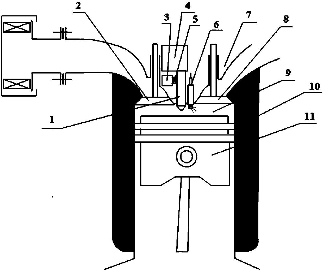
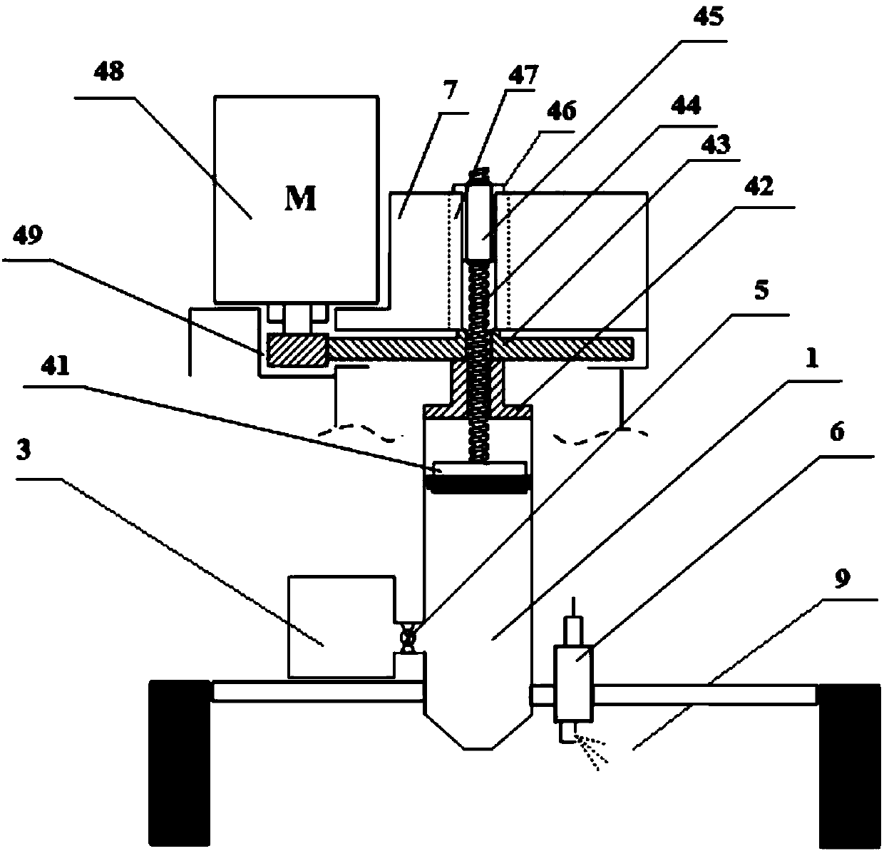
[0036] Such as figure 1 As shown, the nozzle 1 is arranged above the combustion chamber, and the ignition valve 5 is arranged in the channel, which communicates the adiabatic chamber 3 and the nozzle 1, and is used to control the flow of high-temperature and high-pressure gas in the adiabatic chamber 3 and the combustion chamber 9 . The lower part of the nozzle 1 communicates with the combustion chamber 9, so that the high-temperature and high-pressure gas in the adiabatic chamber 3 can be evenly sprayed into the combustion chamber 9, and the combustible mixture in the combustion chamber 9 can be evenly distributed and ignited. The nozzle 1 has high temperature and high pressure gas backflow capability. When the gas pressure in the adiabatic chamber 3 is lower than the gas pr...


PUM


Abstract

The invention discloses an engine circulating ignition energy saving device. The engine circulating ignition energy saving device comprises a nozzle, a heat insulation cavity and an ignition valve. The nozzle is arranged above the combustion chamber and communicates with the communication chamber. The heat insulation cavity communicates with the nozzle through a channel and is used for storing high-temperature and high-pressure gas generated by the combustion chamber. The ignition valve is arranged in the channel and used for controlling opening and closing of the channel. When the ignition valve is opened, the high-temperature and high-pressure gas enters the combustion chamber and is used for igniting mixed gas in the combustion chamber. An engine circulating ignition device is adopted, the high-temperature and high-pressure gas generated through combustion in the combustion chamber can be stored, and when ignition is needed for an air cylinder, the high-temperature and high-pressure gas can be released to achieve space ignition. Meanwhile, the ignition nozzle is designed into the heat insulation cavity with the adjustable volume, a whole engine is equivalent to a changeable compression ratio engine, and the comprehensive performance of the engine is improved. The invention further provides the engine.

Description

technical field [0001] The invention relates to the field of engines, in particular to an energy-saving device that utilizes high-temperature and high-pressure gas to realize engine cycle ignition. Background technique [0002] The engine's combustion chamber is used to convert the chemical energy of the fuel into mechanical energy. The ignition of fuel in the combustion chamber of a gasoline engine depends on several factors: the temperature of the combustible mixture, the type of igniter, the ignition energy, the fuel-air ratio, the input point of ignition energy and the mixing state of the combustible mixture, etc. The combustion chamber of a gasoline engine needs an igniter to Breakdown the combustible mixture to generate electric sparks to trigger the combustion process. At present, gasoline engines generally use spark plug igniters. The ignition system generates a high-voltage pulse that is applied to the spark plug, and a transient high-voltage electric field is gener...

Claims


Application Information

Patent Timeline
Patent Type & Authority Patents(China)
IPC IPC(8): F02P23/00F02B77/00F02N19/02
CPCF02B77/00F02N19/02F02P23/00
Inventor 王军年王岩王治强王庆年王晓昱
Owner JILIN UNIV
Learn More