

Valveless hydraulic servo synchronous system
A hydraulic servo, synchronous system technology, applied in the direction of fluid pressure actuation system components, servo motors, servo meter circuits, etc., to achieve the effect of huge economic and social benefits
- Summary
- Abstract
- Description
- Claims
- Application Information
AI Technical Summary
Problems solved by technology
Method used
Image

Examples
Embodiment 1
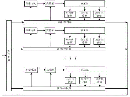
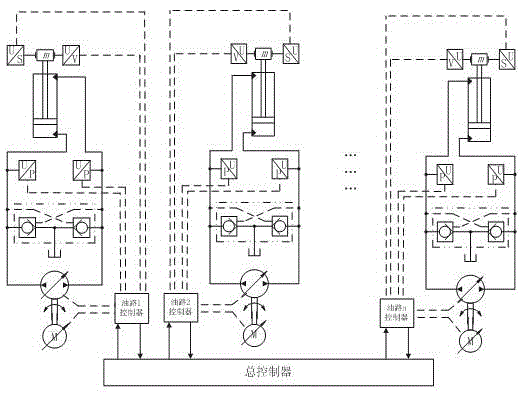
[0024] A valveless hydraulic servo synchronization system that uses multiple oil circuits, and each branch uses sensors to collect data on speed, pressure and displacement. The sub-controller on the oil circuit analyzes the data and then transmits it to the main controller. After the main controller compares, the data is fed back to the sub-controllers, and the sub-controllers act on the servo motor and the pump to adjust the resulting asynchrony.
[0025] Specific control method:
[0026] Take a certain oil circuit as an example and analyze its movement process. Since the oil circuit of the entire branch is exactly the same, the movement process of each oil circuit can be known.
[0027] When the servo motor is started, if the load is too large at this time, it is very likely that the motor cannot rotate, which deviates from the normal operation curve of the motor, and causes the motor to burn more seriously. At this time, reduce the displacement of the pump, that is, reduce its tor...
Embodiment 2
[0036] A valveless hydraulic servo synchronization system uses four oil circuits. Sensors are used on each branch to collect data on speed, pressure and displacement. The sub-controller on the oil circuit analyzes the data and transmits it to the main controller. After the controller compares, the data is fed back to the sub-controller, and the sub-controller acts on the servo motor and the pump to adjust the resulting asynchrony.
[0037] Specific control method:
[0038] Take a certain oil circuit as an example and analyze its movement process. Since the oil circuit of the entire branch is exactly the same, the movement process of each oil circuit can be known.
[0039] When the servo motor is started, if the load is too large at this time, it is very likely that the motor cannot rotate, which deviates from the normal operation curve of the motor, and causes the motor to burn more seriously. At this time, reduce the displacement of the pump, that is, reduce its torque. , The motor...
Embodiment 3
[0048] A valveless hydraulic servo synchronization system, using 6 oil circuits, each branch adopts sensors to collect data on speed, pressure and displacement, and the sub-controller on the oil circuit analyzes the data and then transmits it to the main controller. After the main controller compares, the data is fed back to the sub-controller, and the sub-controller acts on the servo motor and the pump to adjust the resulting asynchrony.
[0049] Specific control method:
[0050] Take a certain oil circuit as an example and analyze its movement process. Since the oil circuit of the entire branch is exactly the same, the movement process of each oil circuit can be known.
[0051] When the servo motor is started, if the load is too large at this time, it is very likely that the motor cannot rotate, which deviates from the normal operation curve of the motor, and causes the motor to burn more seriously. At this time, reduce the displacement of the pump, that is, reduce its torque. , T...
PUM
 Abstract
Description
Claims
Application Information