Full-view-field-based controlling method and apparatus of pan-tilt-zoom camera

A pan-tilt camera and full-view technology, applied in the direction of use feedback control, image analysis, image data processing, etc., can solve problems such as inefficiency, and achieve the effect of simple operation and high adjustment efficiency

Inactive Publication Date: 2016-05-11
SHENZHEN WEISEN SOFTWARE CO LTD
View PDF11 Cites 9 Cited by
  • Summary
  • Abstract
  • Description
  • Claims
  • Application Information

AI Technical Summary

Problems solved by technology

[0006] The object of the present invention is to provide a kind of control method of the pan-tilt camera based on the full fie

Method used


Image

  • Full-view-field-based controlling method and apparatus of pan-tilt-zoom camera
  • Full-view-field-based controlling method and apparatus of pan-tilt-zoom camera
  • Full-view-field-based controlling method and apparatus of pan-tilt-zoom camera

Examples


Embodiment 1

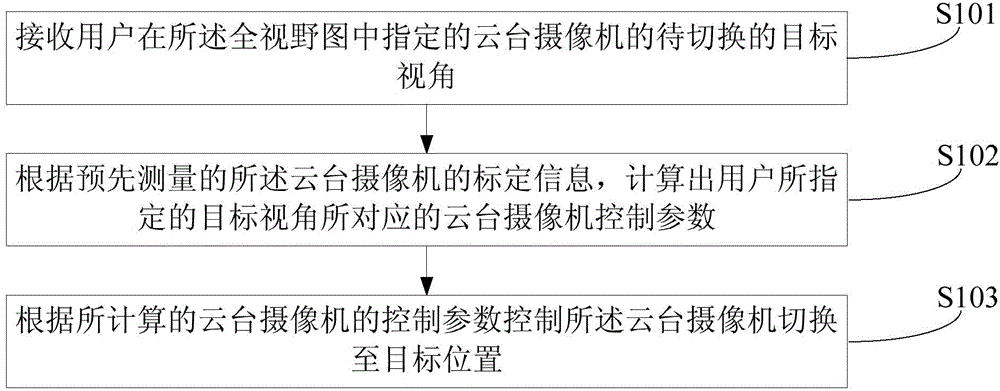
[0025] figure 1 The implementation flow of the camera control method provided by the first embodiment of the present invention is shown, and the details are as follows:

[0026] In step S101, the target angle of view to be switched of the pan-tilt camera designated by the user in the full view diagram is received, the angle of view includes the size of the angle of view and the direction of the angle of view, and the full field of view is the scene where the pan-tilt camera is located A general view of the installation location.

[0027] The full-view diagram is a full-view diagram of the installation position of the scene where the camera is located. Partial images acquired by the pan-tilt camera at different viewing angles are spliced ​​by a computer vision algorithm, which covers a part or all of the field of view of the pan-tilt camera.

[0028] For example, if the camera is set at the entrance of the residential area, according to the rotation range of the camera's pan-...

Embodiment 2

[0041] figure 2 The implementation flow of the camera control method provided by the second embodiment of the present invention is shown, and the details are as follows:

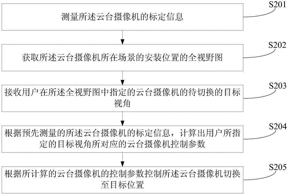
[0042] In step S201, the calibration information of the pan-tilt camera is measured.

[0043] The calibration of described pan-tilt camera, promptly adopts calibration object, by standard computer vision algorithm, can measure the corresponding internal parameter K of pan-tilt camera when double focal length, the internal parameter of camera mainly comprises: effective focal length, optical center, Radial distortion and tangential distortion etc.

[0044] In step S202, a full view view of the installation position of the scene where the pan-tilt camera is located is obtained.

[0045] Specifically, the full-view diagram of the installation position of the scene where the pan-tilt camera is located, the partial images acquired by the pan-tilt camera at different angles of view are spliced ​​by computer vis...

Embodiment 3

[0053] image 3 The implementation flow of the camera control method provided by the third embodiment of the present invention is shown, and the details are as follows:

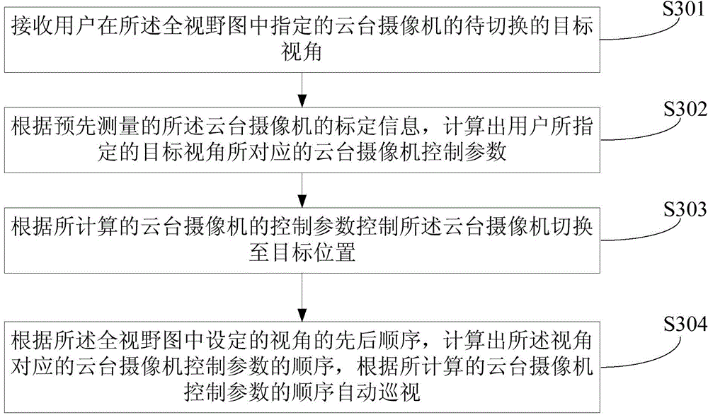
[0054] In step S301, the target angle of view to be switched of the PTZ camera designated by the user in the full field of view is received, the angle of view includes the size and direction of the angle of view, and the full field of view is the scene where the PTZ camera is located A general view of the installation location.

[0055] In step S302, according to the pre-measured calibration information of the pan-tilt camera, the control parameters of the pan-tilt camera corresponding to the target viewing angle specified by the user are calculated.

[0056] In step S303, the pan-tilt camera is controlled to switch to the target position according to the calculated control parameters of the pan-tilt camera.

[0057] Step S301 to step S303 are the same as step S101 to step S103 in the first embodiment.

[...


PUM


Abstract

The invention, which is suitable for the security and protection field, provides a full-view-field-based controlling method and apparatus of a pan-tilt-zoom camera. The method comprises: a user designates a to-be-turned view angle of a pan-tilt-zoom camera on a full-view-field graph, wherein the designated view angle includes a view angle size and a view angle direction; according to calibration information, measured in advance, of the pan-tilt-zoom camera, a pan-tilt-zoom camera control parameter corresponding to the view angle designated by the user is calculated; and the pan-tilt-zoom camera is controlled based on the calculated pan-tilt-zoom camera control parameter, so that the controlled view angel of the pan-tilt-zoom camera is consistent with the view angle designated by the user basically. According to the invention, after the user designated the view angle on the full-view-field graph, the pan-tilt-zoom camera is controlled automatically and rapidly to be at the designated view angle. Therefore, the user can carry out operation simply and visually; the time and labor are saved; the adjusting efficiency is high; and the switching position is accurate.

Description

technical field [0001] The invention belongs to the field of security protection, and in particular relates to a control method and device for a pan-tilt camera based on a full-view image. Background technique [0002] With the development of science and technology, the application of security monitoring is becoming more and more extensive. By setting up monitoring equipment, centralized real-time monitoring of the site can be realized. By applying video image analysis algorithms to security monitoring, automatic alarms can be automatically issued for abnormal conditions, which greatly improves the intelligence of security monitoring. [0003] Since the viewing angle of a camera is limited, in order to monitor multiple angles of a scene, video images acquired by multiple cameras can be used to stitch together, so that real-time scene information from various angles can be viewed. However, this method of acquiring multiple video images for splicing needs to set up multiple c...

Claims


Application Information

Patent Timeline
IPC IPC(8): G05D3/12G06T7/00
Inventor 张岩
Owner SHENZHEN WEISEN SOFTWARE CO LTD
Why Eureka
Try Eureka