Laterally-mounted power-driven operation module

A technology of electric operation and driving parts, applied in the direction of protection switch operation/release mechanism, circuit, electrical components, etc., can solve the problems of low efficiency, increase production cost, and the depth of switch cabinet needs to be deepened, so as to reduce production cost and improve cost. Productivity and cost reduction

Active Publication Date: 2016-05-11
JIANGSU PHONO ELECTRIC
View PDF3 Cites 4 Cited by
  • Summary
  • Abstract
  • Description
  • Claims
  • Application Information

AI Technical Summary

Problems solved by technology

[0003] 1. The existing electric operation module is installed on the top of the circuit breaker, so that the overall height of the circuit breaker is increased, resulting in the need to deepen the depth of the switchgear containing the circuit breaker, increasing the production cost, and the protection performance of the switchgear is required to be improved
[0004] 2. The existing electric operation module is composed of multi-stage gears. The gear processing is difficult, the efficiency is relatively low, and the production cost is increased. Moreover, the torque is transmitted through six-stage gears at different heights, resulting in a higher height of the electric operation module itself. high
[0005] three. Since the existing electric operation module is installed on the top of the outer cover of the circuit breaker, and the handle is inside the electric operation module, the handle needs to be placed inside the connecting rod during installation, so the operating status of the circuit breaker cannot be displayed intuitively and accurately

Method used


Image

  • Laterally-mounted power-driven operation module
  • Laterally-mounted power-driven operation module
  • Laterally-mounted power-driven operation module

Examples


Embodiment Construction

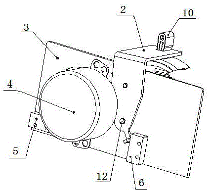
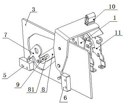
[0031] see Figure 1-2 As shown, the circuit breaker itself includes a handle 10, a bracket 11 and a rotating lever 1. The handle 10 protrudes upwards from the top of the circuit breaker. A bracket 11 and a rotating lever 1 are installed under the handle 10. The lower part of the bracket 11 is fixedly connected to the bottom of the circuit breaker. The bracket 11 supports the rotating lever 1, the handle 10 is fixedly connected with the rotating lever 1, and the handle 10 can rotate around the axis of the rotating lever 1 toward the wire-in end or the wire-out end of the circuit breaker. Such as figure 1 In the middle, the left side is the incoming wire end, and the right side is the outgoing wire end.

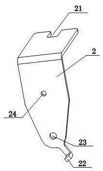
[0032] The present invention includes a side plate 3, a connecting rod transmission part, a motor 4, a handle driving part 2 and the like. The motor 4 rotates one circle in one direction. The motor 4 and the connecting rod transmission part are all located on the same side ...


PUM


Abstract

The invention discloses a laterally-mounted power-driven operation module used for a molded case circuit breaker in a low-voltage electrical product. A motor and a connection rod transmission part are both arranged on the same side of a handle; when the motor is not energized, the handle is at a tripping position, the connection rod transmission part is at a position touched with a first positional signal contact point, and a handle driving element is at a position which is not touched with a second positional signal contact point; after the motor is energized and the handle is at a switch-off position, the first positional signal contact point is at a released normally-open status, and the handle driving element is at the position which is not touched with the second positional signal contact point; after the motor continuously rotates and the handle is at a switch-on position, the first positional signal contact point is arranged at the position which is not touched, and the second positional signal contact point is touched and closed by the handle driving element; and after the motor continuously rotates again, the connection rod transmission part is at the position touched with the first positional signal contact point, and the motor is in a stop status. When the laterally-mounted power-driven operation module is in manual operation, the manual operation is achieved without configuring an extra part, and the manual operation and the power-driven operation are not affected with each other.

Description

technical field [0001] The invention relates to a molded case circuit breaker in the field of low-voltage electrical technology, in particular to an electric operation module for the molded case circuit breaker. Background technique [0002] The circuit breaker with electric operation module can ensure the continuous operation of the power system, and the circuit breaker with electric operation module can realize remote control function, which is convenient for the operator to remotely control the circuit breaker. At present, the existing electric operation module is generally composed of an outer cover, a motor, a gear, an eccentric wheel, a connecting rod, some stamping parts and some standard parts. It presents a structure of up and down installation, the uppermost part is the motor, the gear is located in the middle of the motor and the eccentric wheel, there are 6 gears located at different heights, the eccentric wheel and the connecting rod linked with it are located a...

Claims


Application Information

Patent Timeline
Patent Type & Authority Applications(China)
IPC IPC(8): H01H71/10H01H71/04H01H71/02
CPCH01H71/0207H01H71/04H01H71/10
Inventor 陈咸李冰燕肖爽
Owner JIANGSU PHONO ELECTRIC
Why Eureka
Try Eureka