An overcurrent or short circuit fault signal isolation detection circuit and its design method

A short-circuit fault and signal isolation technology, applied in the direction of measuring electricity, measuring electrical variables, measuring current/voltage, etc., can solve problems such as being unsuitable for DC or low-frequency current signal measurement, the protection speed cannot meet the requirements, and the response speed is not fast enough. , to achieve the effect of low power consumption, low power consumption and convenient implementation

Active Publication Date: 2018-04-13
XIAN UNIV OF SCI & TECH
View PDF5 Cites 0 Cited by
  • Summary
  • Abstract
  • Description
  • Claims
  • Application Information

AI Technical Summary

Problems solved by technology

[0004] The series resistance type protection circuit needs a current sampling resistor. If the sampling resistor is relatively large, a large current will flow through the resistor, which increases the extra power consumption of the circuit. If a small resistance current sampling resistor is used, the signal needs to be processed. Amplification, which will complicate the circuit structure and increase the cost; another problem with sampling current signals with series resistors is that isolation cannot be achieved
[0005] Current sensor type detection circuit, due to the limitation of bandwidth, the protection speed may not meet the requirements, and the general current sensor is relatively expensive
For example, the most commonly used current sensor - Hall current sensor, its price is high, the response speed is not fast enough, and the accuracy is low when the current is small, and most current sensors need an external power supply to work normally, which makes the circuit structure complicated.
For the current transformer detection circuit, it is not suitable for the measurement of DC or low-frequency current signals, and the application is limited

Method used


Image

  • An overcurrent or short circuit fault signal isolation detection circuit and its design method
  • An overcurrent or short circuit fault signal isolation detection circuit and its design method

Examples


Embodiment Construction

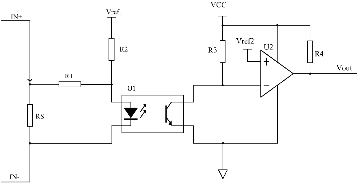
[0043] Such as figure 1 As shown, the overcurrent or short circuit fault signal isolation detection circuit of the present invention includes an optocoupler isolator U1 and a comparator U2, and a resistor RS, a resistor R1, a resistor R2, a resistor R3 and a resistor R4, and one end of the resistor R1 is connected to One end of the resistor RS is connected to the positive voltage input terminal IN+ of the over-current or short-circuit fault signal isolation detection circuit 3, the anode of the optocoupler isolator U1 is connected to the other end of the resistor R1, and is connected to the second end of the resistor R1 through the resistor R2. The output terminal Vref1 of a reference power supply is connected, the cathode of the optocoupler isolator U1 is connected to the other end of the resistor RS and is the negative voltage input terminal IN- of the overcurrent or short circuit fault signal isolation detection circuit 3, the The collector of the optocoupler isolator U1 is...


PUM


Abstract

The invention discloses an overcurrent or short-circuit fault signal isolation detection circuit comprising an optical coupling isolator U1, a comparator U2 and a resistor RS, a resistor R1, a resistor R2, a resistor R3 and a resistor R4. One end of the resistor R1 is connected with one end of the resistor RS. The anode of the optical coupling isolator U1 is connected with the other end of the resistor R1 and is connected with the output end Vref1 of a first reference power supply through the resistor R2. The cathode of the optical coupling isolator U1 is connected with the other end of the resistor RS. The collection electrode of the optical coupling isolator U1 is connected with the out-phase input end of the comparator U2 and is connected with the output end VCC of a power supply through the resistor R3. The in-phase input end of the comparator U2 is connected with the output end Vref2 of a second reference power supply. The invention also discloses a design method of the overcurrent or short-circuit fault signal isolation detection circuit. The overcurrent or short-circuit fault signal isolation detection circuit is convenient to realize, low in cost, stable in working and high in reliability so that overcurrent or short-circuit faults can be effectively detected.

Description

technical field [0001] The invention belongs to the technical field of overcurrent or short circuit fault protection, in particular to an overcurrent or short circuit fault signal isolation detection circuit and a design method thereof. Background technique [0002] With the rapid development of electronic technology, the design of switching converter protection circuit has become a crucial part to ensure the safe operation of the converter. [0003] At present, there are many protection schemes for switching converters, such as over-current or short-circuit protection circuits, over-voltage protection circuits, and so on. There are many similarities between the overcurrent and short circuit of the circuit, and there are many essential differences at the same time. Overcurrent means that the current flowing through the load exceeds the rated output current of the power supply. If the device works in the overcurrent state for a long time, it will damage the device, and the p...

Claims


Application Information

Patent Timeline
Patent Type & Authority Patents(China)
IPC IPC(8): H02H3/08G01R19/165G01R31/02
CPCG01R19/16533G01R31/50H02H3/08
Inventor 刘树林徐丹丹王朝英汪倩倩黄治员翠平郭瑞峰
Owner XIAN UNIV OF SCI & TECH
Why Eureka
Try Eureka