Fling-cut switch array-based energy router and fling-cut switch control method

A switching switch and control method technology, applied in circuit devices, AC network circuits, electrical components, etc., can solve problems such as power loss in load circuits and arcs generated by magnetic latching relays, and achieve improved coordination control, simple structure, and good application. Foreground effect

Inactive Publication Date: 2016-05-11
XI AN JIAOTONG UNIV
View PDF2 Cites 7 Cited by
  • Summary
  • Abstract
  • Description
  • Claims
  • Application Information

AI Technical Summary

Problems solved by technology

Similar to other mechanical electric shock switches such as contactors and circuit breakers, magnetic latching relays will generate arcs when they are turned on or off; in addition, the switching process takes a certain amount of time, which will cause the load circuit to lose power

Method used


Image

  • Fling-cut switch array-based energy router and fling-cut switch control method
  • Fling-cut switch array-based energy router and fling-cut switch control method
  • Fling-cut switch array-based energy router and fling-cut switch control method

Examples


Embodiment Construction

[0035] The present invention is described in further detail below in conjunction with accompanying drawing:

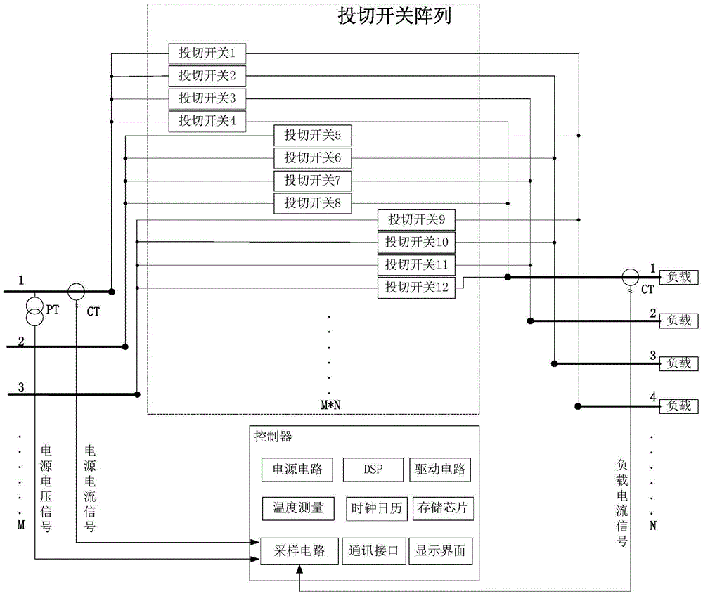
[0036] see figure 1 , the present invention includes a controller and a switching switch array. The controller mainly includes a power supply circuit, a sampling circuit, a drive circuit, a communication interface, a display interface and a memory chip. The switching switch array is composed of multiple switching switches, and each switching switch can perform independent switching operations under the control of the controller to realize the connection or disconnection of the corresponding circuit. The invention is applied in a micro-grid to complete the coordinated control of energy distribution and improve the economy of micro-grid operation.

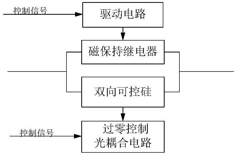
[0037] figure 2 It is the structure diagram of each switching switch in the switching switch array, the magnetic latching relay is connected in parallel with the bidirectional thyristor, the magnetic latching relay is tri...


PUM


Abstract

The invention discloses a fling-cut switch array-based energy router and a fling-cut switch control method. The voltage and the current of all distributed power supplies and the load of all branches are monitored in real time with a digital signal processor as a core, an optimal circuit topology structure mode is determined through integrating the output ability, the real time price, the load characteristic and other factors of all the distributed power supplies, and the fling and cutting of fling-cut switches in a fling-cut switch array is adaptively controlled, so coordinative control of energy distribution is realized, and the micro-grid running economy is improved. The fling-cut switch is formed through parallel connection of a magnetic latching relay and a bidirectional silicon controlled rectifier, voltage zero-crossing flinging and current zero-crossing cutting are realized through the bidirectional silicon controlled rectifier, continuous load current goes through the magnetic latching relay, and the silicon controlled rectifier only works for a short time in circuit switching, so the problem of large loss of the silicon controlled rectifier due to long-term working is avoided, and the inrush current problem in flinging and arc generated in circuit breaking are avoided.

Description

【Technical field】 [0001] The invention belongs to electrical equipment for low-voltage power distribution, and relates to a controller and a switch array, in particular to an energy router based on the switch array and a control method for the switch. 【Background technique】 [0002] In recent years, distributed power sources such as electric vehicles and solar energy have received more and more attention and applications. With the increase in capacity and the expansion of scope, the research on microgrids formed by small-capacity distributed power sources has attracted more attention. Distributed power sources in this type of microgrid mainly include wind turbines, photovoltaic cells, fuel cells, micro gas turbines, etc. [0003] As a bridge between distribution network and distributed power, microgrid is the frontier and focus of international energy and power technology development. As a beneficial supplement to the large power grid, the microgrid is an important link to ...

Claims


Application Information

Patent Timeline
Patent Type & Authority Applications(China)
IPC IPC(8): H02J3/00
CPCH02J3/005H02J3/00
Inventor 张国钢景培王浩耿英三王建华
Owner XI AN JIAOTONG UNIV
Why Eureka
Try Eureka