Safe torque off (STO) control circuit and system

A technology for controlling circuits and circuits, applied in electrical components, output power conversion devices, etc., can solve the problem of speed-adjustable electric equipment without STO control circuits

Active Publication Date: 2016-05-11
INVT POWER ELECTRONICS SUZHOU CO LTD
View PDF3 Cites 10 Cited by
  • Summary
  • Abstract
  • Description
  • Claims
  • Application Information

AI Technical Summary

Problems solved by technology

[0004] However, there is currently no STO control circuit to realize the reliable STO function of adjustable-speed electric equipment

Method used


Image

  • Safe torque off (STO) control circuit and system
  • Safe torque off (STO) control circuit and system
  • Safe torque off (STO) control circuit and system

Examples


Embodiment 1

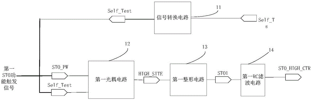
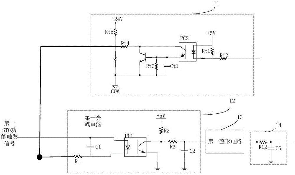
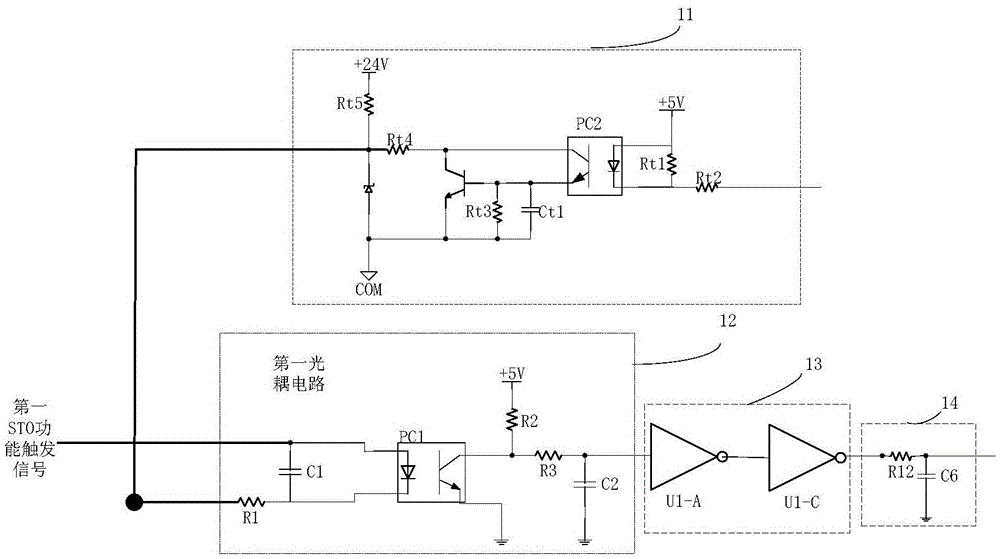
[0081] See figure 1 , which shows a schematic diagram of the logical structure of the STO control circuit provided in the present application, the STO control circuit includes: a signal conversion circuit 11 , a first optocoupler circuit 12 , a first shaping circuit 13 and a first RC filter circuit 14 .

[0082] The input terminal of the signal conversion circuit 11 is used for receiving the first narrow pulse signal.

[0083] In this embodiment, the first narrow pulse signal is used to realize the self-test of the STO control circuit.

[0084] In this embodiment, the first narrow pulse signal may specifically be output by the control module of the electric device corresponding to the STO control circuit.

[0085] The first input end of the first optocoupler circuit 12 is connected to the output end of the signal conversion circuit 11, the second input end of the first optocoupler circuit 12 is used to receive the first STO function trigger signal, the The output end of the ...

Embodiment 2

[0121] In this embodiment, another STO control circuit is expanded on the basis of the STO control circuit shown in Embodiment 1, please refer to Figure 7 , on the basis of the STO control circuit shown in Embodiment 1, it also includes: a second optocoupler circuit 15 having the same structure as the first optocoupler circuit 12; a second shaping circuit 15 having the same structure as the first shaping circuit 13 Circuit 16; a second RC filter circuit 17 having the same structure as the first RC filter circuit 14.

[0122] The first input end of the second optocoupler circuit 15 is connected to the output end of the signal conversion circuit 11, and the second input end of the second optocoupler circuit 15 is used to receive the first STO function trigger signal, The output end of the second optocoupler circuit 15 is connected to the input end of the second shaping circuit 16 , and the output end of the second shaping circuit 16 is connected to the input end of the second R...

Embodiment 3

[0145] In this embodiment, a STO control system is shown, please refer to Figure 10 , including electric equipment 151 and STO control circuit 152 .

[0146] For the composition and electrical principle of the STO control circuit 152 , please refer to the STO control circuit shown in Embodiment 1, which will not be repeated here.

[0147] It should be noted that the STO control circuit 152 implements the input of the first STO function trigger signal STO_PW through the emergency stop switch SW1 . The emergency stop switch SW1 is connected to the second input terminal of the first optocoupler circuit 12 . Among them, the emergency stop switch SW1 is a normally closed switch, which is disconnected when pressed to trigger the STO function.

[0148] When the STO function of the STO control circuit 152 is not triggered, the emergency stop switch SW1 is in a closed state, and the first STO function trigger signal STO_PW received by the second input end of the first optocoupler ci...


PUM


Abstract

The application provides a safe torque off (STO) control circuit and system. The STO control circuit comprises a signal conversion circuit, a first photocoupling circuit, a second photocoupling circuit, a first NOT gate, a second NOT gate, a third NOT gate, a fourth NOT gate, a first RC filter circuit and a second RC filter circuit, wherein the first photocoupling circuit comprises a first resistor, a second resistor, a third resistor, a first capacitor, a second capacitor, a first diode, a second diode, a third diode, a fourth diode, a first voltage stabilization diode and a first isolation photocoupler, and the second photocoupling circuit comprises a fourth resistor, a fifth resistor, a sixth resistor, a third capacitor, a fourth capacitor, a fifth diode, a sixth diode, a seventh diode, an eighth diode, a second voltage stabilization diode and a second isolation photocoupler. In the application, the STO control circuit provided by the invention is used for achieving an STO function and circuit self-detection.

Description

technical field [0001] This application relates to the field of power electronics, in particular to an STO (SafeTorqueOff, Safe Torque Off) control circuit and system. Background technique [0002] At present, with the application of adjustable-speed electric equipment (such as frequency converter) in daily life and industry more and more widely, the safety function requirements for adjustable-speed electric equipment are getting higher and higher. [0003] For the adjustable-speed electric equipment that controls the motor, when a fault such as overspeed or unexpected start occurs, it is necessary to reliably and forcibly shut down the output torque of the motor of the adjustable-speed electric equipment to meet safety requirements. The above operations can be realized by the STO function. If the adjustable-speed electric equipment has the STO function, the safety function of the adjustable-speed electric equipment will be greatly improved. [0004] However, currently ther...

Claims


Application Information

Patent Timeline
Patent Type & Authority Applications(China)
IPC IPC(8): H02M1/32
CPCH02M1/32H02M1/325
Inventor 梁剑龙
Owner INVT POWER ELECTRONICS SUZHOU CO LTD
Why Eureka
Try Eureka