Control device for DC output potential of power amplifier

A power amplifier and DC output technology, which is applied in the direction of improving the amplifier to reduce temperature/power supply voltage changes, can solve the problems of circuit self-excitation performance and reduction, and achieve the effect of improving performance and avoiding self-excitation

Active Publication Date: 2018-09-28
GUANGZHOU TIME ART AUDIO TECH CO LTD
View PDF6 Cites 0 Cited by
  • Summary
  • Abstract
  • Description
  • Claims
  • Application Information

AI Technical Summary

Problems solved by technology

[0003] The purpose of the present invention is to provide a control device for the DC output potential of the power amplifier, aiming at the problems of transient intermodulation distortion caused by the negative feedback design of the power amplifier in the prior art and easy to cause self-excitation and performance degradation of the circuit. It adjusts the bias voltage through active temperature control to achieve the purpose of controlling the DC output potential, thereby avoiding transient intermodulation distortion and possible self-excitation caused by negative feedback, and also improving the performance of the amplifier circuit

Method used


Image

  • Control device for DC output potential of power amplifier

Examples


Embodiment Construction

[0020] In order to facilitate the understanding of those skilled in the art, the present invention will be further described below in conjunction with the accompanying drawings and embodiments.

[0021] Typical Power Amplifier

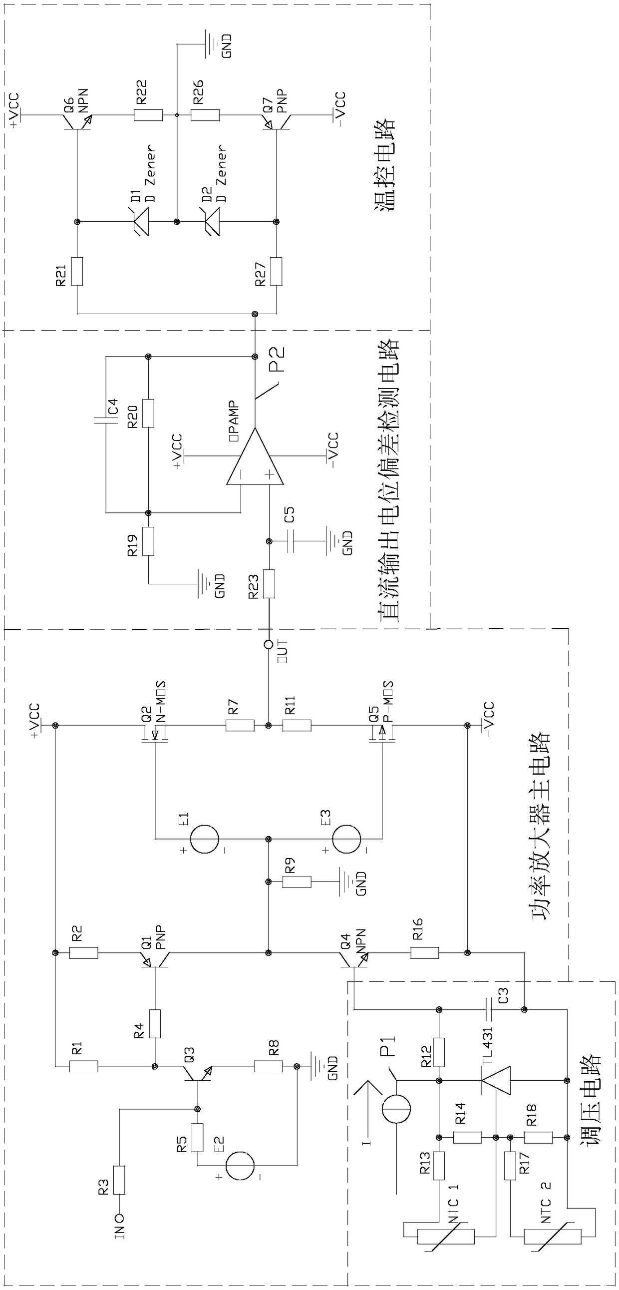
[0022] see figure 1 , the main circuit of a typical power amplifier without large-loop negative feedback is as figure 1 As shown in "Power Amplifier Main Circuit" in the middle, +VCC is a positive voltage, -VCC is a negative voltage, and GND is ground or 0 volts. The signal is input through the port IN, and R3 is the input resistor. E2 is a voltage source that provides bias voltage for transistor Q3. Resistor R1, resistor R3, resistor R5, voltage source E2, transistor Q3, and resistor R8 form the first stage of voltage amplification. R4 is the input resistance of the second-stage voltage amplification, and forms the second-stage voltage amplification together with the resistor R2, transistor Q1, transistor Q4, and resistor R16. R9 is the load resi...


PUM


Abstract

A control device for a direct-current output potential of a power amplifier. The control device is implemented on the basis of an active temperature control bias circuit. In the active temperature control bias circuit, a direct-current output potential deviation detection circuit detects a direct-current output potential deviation value of the power amplifier, and a temperature control circuit correspondingly heats or cools a voltage regulating circuit according to the detected direct-current output potential deviation value. The voltage regulating circuit correspondingly regulates, according to the heating or cooling of the temperature control circuit, a bias voltage of a device generating a temperature drift in the power amplifier. Accordingly, the bias voltage can be regulated by means of active temperature control, so as to achieve the purpose of controlling the direct-current output potential, self-excitation and transient intermodulation distortion caused by negative feedback in the prior art are avoided, and the performance of an amplifier circuit is improved.

Description

technical field [0001] The invention relates to the field of power amplifier control, in particular to a control device for the DC output potential of the power amplifier, which realizes the stability control and performance improvement of the DC output potential of the power amplifier based on an active temperature control bias circuit. Background technique [0002] Due to the temperature drift characteristics of electronic components, especially the significant temperature drift characteristics of semiconductor components, the power amplifier works at different ambient temperatures, and its own heating during the work process causes the operating temperature of the components to change, which will cause the DC output of the power amplifier The potential changes with temperature, which makes the power amplifier work unstable and may even burn out the load. The existing control method for stabilizing the DC output potential of the power amplifier generally achieves the goal ...

Claims


Application Information

Patent Timeline
Patent Type & Authority Patents(China)
IPC IPC(8): H03F1/30
CPCH03F1/30
Inventor 刘广斌
Owner GUANGZHOU TIME ART AUDIO TECH CO LTD
Why Eureka
Try Eureka