Signal processing method and electronic device

An electronic device and signal processing technology, which is applied in the field of communication, can solve the problems that the signal reception performance cannot be guaranteed, and the radiation angle of the directional antenna scheme cannot be changed, so as to improve the signal reception performance and ensure the reception performance.

Active Publication Date: 2016-05-11
LENOVO (BEIJING) CO LTD
View PDF7 Cites 9 Cited by
  • Summary
  • Abstract
  • Description
  • Claims
  • Application Information

AI Technical Summary

Problems solved by technology

[0003] Although the omnidirectional antenna scheme has a large radiation angle, it cannot guarantee the signal reception performance in a specific direction (the radiation distance is small), and if a directional antenna is used, although it can guarantee the signal reception performance in the direction, but due to the directional antenna The radiation angle of the scheme cannot be changed, so it can only guarantee the signal receiving performance in a specific receiving direction (corresponding to the radiation angle), and cannot guarantee the signal receiving performance in multiple receiving directions
[0004] In summary, there is no effective solution for how to improve the signal receiving performance of the antenna in different directions

Method used


Image

  • Signal processing method and electronic device
  • Signal processing method and electronic device
  • Signal processing method and electronic device

Examples


Embodiment 1

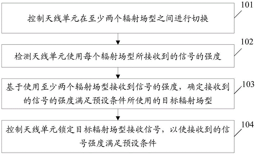
[0045] This embodiment records a signal processing method, see figure 1 , including the following steps:

[0046] Step 101, controlling the antenna unit to switch between at least two radiation patterns.

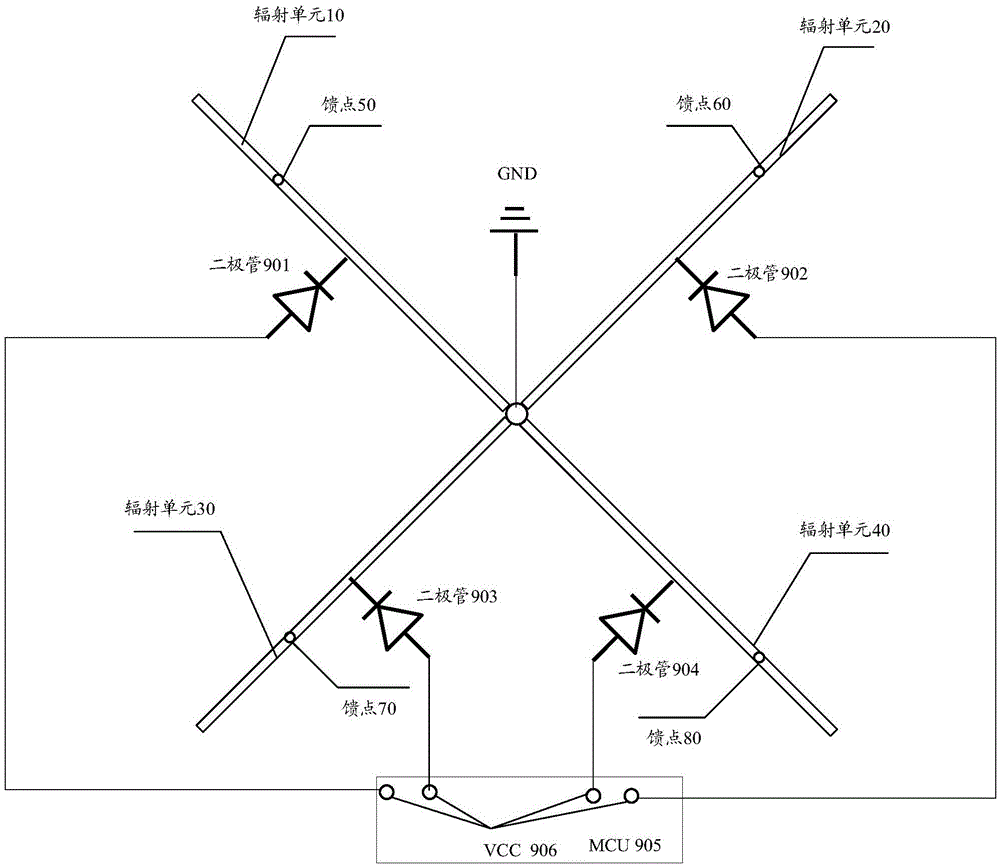
[0047] The electronic equipment is provided with an antenna unit and a control unit, and the antenna unit includes at least two radiators; the control unit switches and shields part of the radiators in the at least two radiators constituting the antenna unit, so that the at least two radiators are in an unshielded state. The radiators in different states form different effective radiation units; wherein, when the effective radiation units formed by at least two radiation units are different, the directional radiation patterns formed by the at least two radiation units are also correspondingly different.

[0048] The control unit includes a microcontroller, a switch and a DC power supply, the switch and the radiator are arranged in one-to-one correspondence, and the DC power...

Embodiment 2

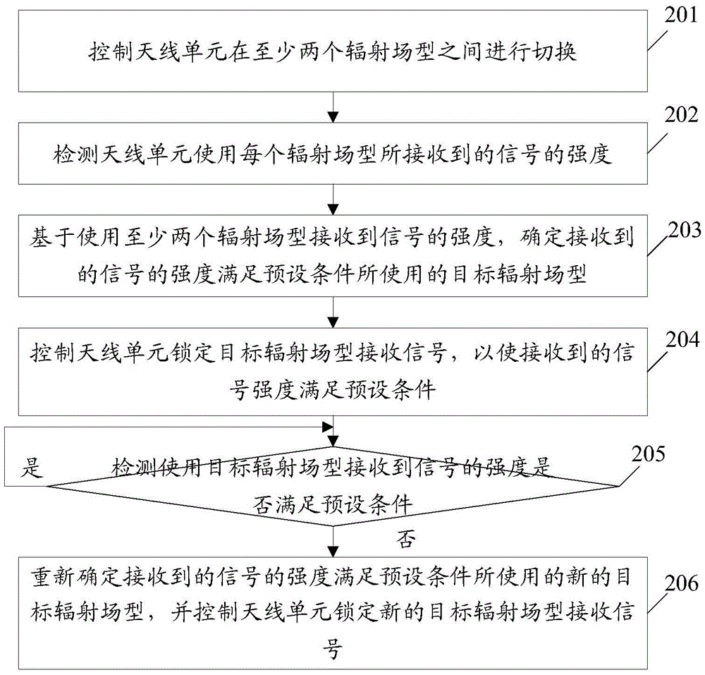
[0077] For the situation recorded in Embodiment 1, when the antenna unit is locked to use the target radiation pattern to receive the signal from the signal source, if the position of the antenna unit relative to the signal source changes, or the signal emission of the signal source itself changes ( For example, if the transmitting antenna of the signal source is a directional antenna and the direction of the antenna changes), it will cause the strength of the signal received by the antenna unit to use the target radiation pattern to change. This embodiment will describe the processing of the above situation.

[0078] This embodiment records a signal processing method, see image 3 , including the following steps:

[0079] Step 201, controlling the antenna unit to switch between at least two radiation patterns.

[0080] Step 202, detecting the strength of signals received by the antenna unit using at least two radiation patterns.

[0081] Step 20, 3, based on the strengths o...

Embodiment 3

[0089] For the situation recorded in Embodiment 1, when the antenna unit is locked to use the target radiation pattern to receive the signal from the signal source, if the position of the antenna unit relative to the signal source changes, or the signal emission of the signal source itself changes ( For example, if the transmitting antenna of the signal source is a directional antenna and the direction of the antenna changes), it will cause the strength of the signal received by the antenna unit to use the target radiation pattern to change. This embodiment will describe the processing of the above situation.

[0090] This embodiment records a signal processing method, see Figure 4 , including the following steps:

[0091] Step 301, controlling the antenna unit to switch between at least two radiation patterns.

[0092] Step 302, detecting the strength of signals received by the antenna unit using at least two radiation patterns.

[0093] Step 303, based on the strengths of...


PUM


Abstract

The invention discloses a signal processing method and an electronic device. The method comprises steps of controlling an antenna unit to be switched between at least two radiation field types and detecting intensity of signals received by the antenna unit by use of the radiation field types; determining a target radiation field type satisfying preset conditions of intensity of the received signal based on the intensity of the received signal by use of the radiation field types; and controlling the antenna unit to lock the received signal of the target radiation field type so as to allow the intensity of the received signal to satisfy the preset conditions. In this way, signal receiving performance of an antenna in different directions can be improved.

Description

technical field [0001] The invention relates to communication technology, in particular to a signal processing method and electronic equipment. Background technique [0002] At present, the wireless communication scheme basically adopts the antenna design with fixed radiation field type, such as mobile phone, computer and other wireless communication terminals adopt omnidirectional antenna scheme, and network equipment such as router adopts directional antenna scheme; [0003] Although the omnidirectional antenna scheme has a large radiation angle, it cannot guarantee the signal reception performance in a specific direction (the radiation distance is small), and if a directional antenna is used, although the signal reception performance in the direction can be guaranteed, but due to the directional antenna The radiation angle of the solution cannot be changed, so it can only guarantee the signal receiving performance in a specific receiving direction (corresponding to the ra...

Claims


Application Information

Patent Timeline
IPC IPC(8): H04B1/40H01Q3/34
CPCH01Q3/34H04B1/401
Inventor 苗蕾樊小军
Owner LENOVO (BEIJING) CO LTD
Why Eureka
Try Eureka