Wireless communication system idle channel detection method and wireless communication system idle channel detection system

A technology of idle channel detection and wireless communication system, applied in wireless communication, transmission system, transmission monitoring and other directions

Active Publication Date: 2016-05-11
ZTE CORP
View PDF5 Cites 25 Cited by
  • Summary
  • Abstract
  • Description
  • Claims
  • Application Information

AI Technical Summary

Problems solved by technology

[0008] The present invention provides an idle channel detection method and system used in a wireless communicati

Method used


Image

  • Wireless communication system idle channel detection method and wireless communication system idle channel detection system
  • Wireless communication system idle channel detection method and wireless communication system idle channel detection system

Examples


application example 1

[0102] Application example 1: The transmitting station transmits beamformed data with fixed power.

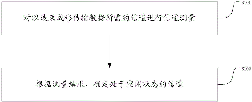
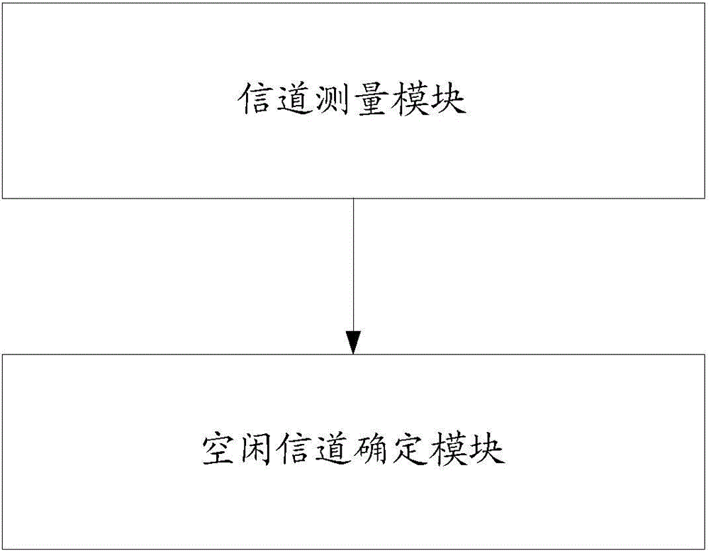
[0103] The sending station performs channel measurement on the channel required to transmit data with beamforming to determine whether the channel is in an idle state. The conditions for determining that the channel is in an idle state are:

[0104] 1) If it is detected that the signal strength opposite to the transmission direction of the data to be sent is less than or equal to the threshold A1;

[0105] 2) If it is detected that the signal strength in the same transmission direction as the data to be sent is less than or equal to the threshold A2;

[0106] When above-mentioned conditions 1) and 2) are met simultaneously, it can be determined that the channel is in an idle state, wherein said threshold A1 and threshold A2 are set according to the transmission bandwidth; above-mentioned threshold A1 and threshold A2 can be dynamically adjusted according to the transmission ban...

application example 2

[0108] Application example 2: The transmitting station transmits beamformed data with variable power.

[0109] The sending station performs channel measurement on the channel required to transmit data with beamforming to determine whether the channel is in an idle state. The conditions for determining that the channel is in an idle state are:

[0110] 1) If it is detected that the signal strength opposite to the transmission direction of the data to be sent is less than or equal to the threshold A1;

[0111] 2) If it is detected that the signal strength in the same transmission direction as the data to be sent is less than or equal to the threshold A2;

[0112] 3) Calculating the transmit power of the beamforming data that satisfies the set modulation and coding rate, if the transmit power is the transmit power supported by the sending site;

[0113] The calculation of the transmit power of the beamforming data satisfying the set modulation and encoding rate includes:

[011...

application example 3

[0123] Application Example 3: A transmitting station transmits beamformed data to multiple receiving stations at a fixed power.

[0124] The sending station performs channel measurement on the channel required to transmit data with beamforming to determine whether the channel is in an idle state. The conditions for determining that the channel is in an idle state are:

[0125] 1) If it is detected that the signal strength opposite to the transmission direction of the data to be sent is less than or equal to the threshold A1;

[0126] 2) If it is detected that the signal strength in the same transmission direction as the data to be sent is less than or equal to the threshold A2;

[0127] When above-mentioned conditions 1) and 2) are met simultaneously, it can be determined that the channel is in an idle state, wherein said threshold A1 and threshold A2 are set according to the transmission bandwidth; above-mentioned threshold A1 and threshold A2 can be dynamically adjusted acco...


PUM


Abstract

The invention discloses a wireless communication system idle channel detection method and a wireless communication system idle channel detection system. The wireless communication system idle channel detection method is characterized in that channel measurement of channels required by beam forming transmission data can be carried out, and the channels in the idle state can be determined. The wireless communication system idle channel detection system comprises a channel measuring module, which is used for channel measurement of the channels required by the beam forming transmission data; and an idle channel determining module, which is used for determining the channels in the idle states according to the channel measurement result. The data transmission probability of the transmission stations can be improved.

Description

technical field [0001] The invention relates to the field of channel detection, in particular to a method and system for detecting an idle channel in a wireless communication system. Background technique [0002] At present, in the wireless network field, the wireless local area network (WLAN) develops rapidly, the demand for WLAN coverage is increasing day by day, the application of WLAN is more extensive, and the deployment density of WLAN is also increasing rapidly. [0003] The IEEE802.11 technical definition consists of an access point (access point, AP) and multiple stations (Station, STA for short) associated with the AP to form a basic service set (basic service set, BSS for short). The station uses the carrier sense multiple access mechanism CSMA / CA (CSMAwithCollisionAvoidance) with collision avoidance to make multiple stations share the wireless channel. The working principle of CSMA / CA is: the sending end first detects whether the channel is idle, and if it detec...

Claims


Application Information

Patent Timeline
IPC IPC(8): H04B17/00H04W24/08
CPCH04B17/26H04B17/309H04B17/318H04B17/00H04W72/54H04W16/02H04W24/08H04W24/10H04W28/18H04W72/02
Inventor 孙波吕开颖张力方永刚田开波
Owner ZTE CORP
Why Eureka
Try Eureka