

Omnidirectional wheel, moving device and control method of moving device
A technology of motion device and omnidirectional wheel, applied in the control of motion device and motion device, omnidirectional wheel can solve the problems of uncontrollable and low braking performance, and achieve the effect of preventing random rotation and increasing resistance.
- Summary
- Abstract
- Description
- Claims
- Application Information
AI Technical Summary
Problems solved by technology
Method used
Image

Examples
Embodiment Construction
[0044] In order to make the object, technical solution and advantages of the present invention clearer, the implementation manner of the present invention will be further described in detail below in conjunction with the accompanying drawings.
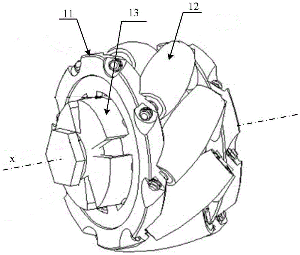
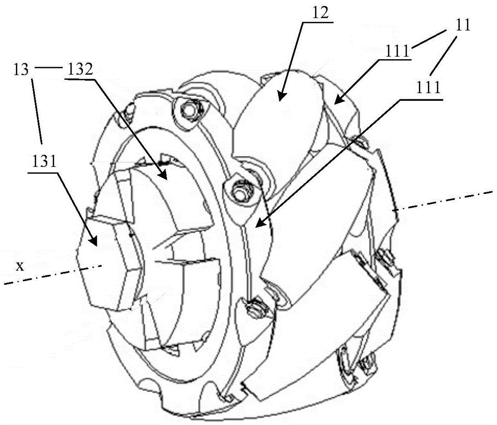
[0045] figure 1 It is a structural schematic diagram of an omnidirectional wheel shown in an embodiment of the present invention. The omni wheel can include:
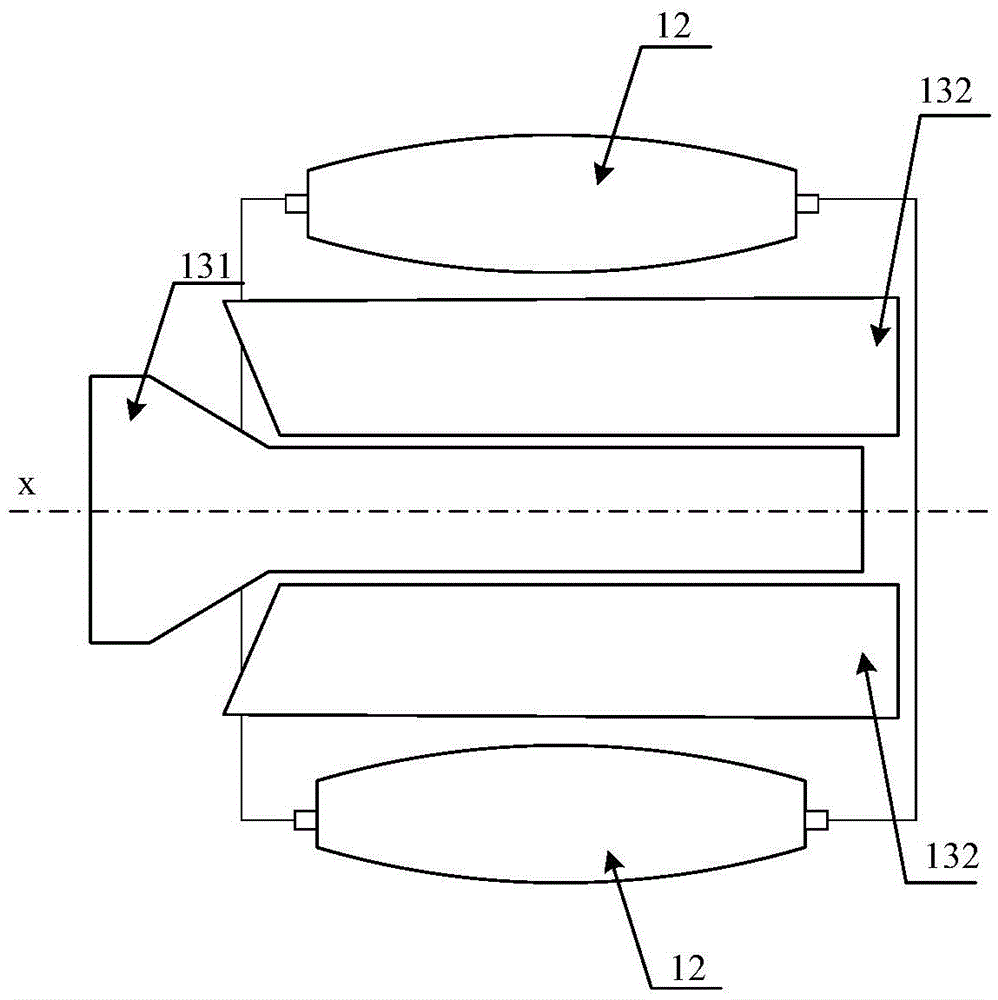
[0046] The central wheel 11 and a plurality of peripheral wheels 12 are arranged in an array around the axis x of the central wheel 11 .
[0047] The central wheel 11 is provided with a peripheral wheel brake assembly 13, which can control the resistance of the peripheral wheel 12 when it rotates.
[0048] To sum up, the omnidirectional wheel provided by the embodiment of the present invention solves the problem of the movement device in the related art by setting the peripheral wheel braking assembly on the center wheel to control the resistance of the peripheral wheels aroun...
PUM
 Abstract
Description
Claims
Application Information