Scraper mechanism and scraper conveyor and feeding crusher comprising scraper mechanism

A conveyor and scraper technology, which is applied in the field of scraper conveyors, bulk material conveying systems, material conveying systems, and scraper mechanisms, and can solve problems such as easy wear, broken joints, and damage to traction chains

Active Publication Date: 2016-05-18
ANHUI NAIKE EXTRUSION SCI & TECH
View PDF9 Cites 5 Cited by
  • Summary
  • Abstract
  • Description
  • Claims
  • Application Information

AI Technical Summary

Problems solved by technology

In practice, the researchers found that there are at least the following technical problems in the prior art: 1). During work, with the continuous wear of the scraper and the drag chain, the wear of the connection between the scraper and the drag chain will also be relatively Severe, resulting in a decrease in the safety factor of the connection between the scraper and the traction chain, and in the event of an accident such as jamming, it will directly cause the connection to break and cause an accident in the equipment; 2). The scraper conveying of the existing feed crusher The upper and lower surfaces of the scraper are generally flat, with a large contact area with the bottom plate, which is easy to wear. When scraping the material, only one layer is scraped, and there is almost no material above the scraper during the conveying process, and the material and the bottom plate The friction between the scraper and the bottom plate is much greater than the friction between t

Method used


Image

  • Scraper mechanism and scraper conveyor and feeding crusher comprising scraper mechanism
  • Scraper mechanism and scraper conveyor and feeding crusher comprising scraper mechanism
  • Scraper mechanism and scraper conveyor and feeding crusher comprising scraper mechanism

Examples


Embodiment Construction

[0060] In order to enable those skilled in the art to better understand the various technical solutions involved in the present invention, the present invention will be further described in detail below in conjunction with the accompanying drawings and specific embodiments. It should be noted that, in the case of no conflict, the embodiments in this application and the specific technical features described in the embodiments can be combined in any suitable way; The possible combinations are not further described, as long as they do not violate the idea of ​​the present invention, they should also be regarded as the content disclosed in the present invention.

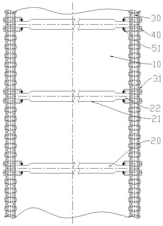
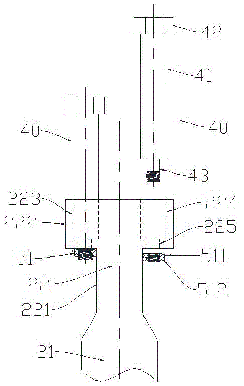
[0061] Such as figure 1 and figure 2 as shown, figure 1 It is a schematic diagram of the structural principle of the scraper mechanism provided by a specific embodiment of the present invention; figure 2 for figure 1 Schematic diagram of a partially enlarged structure at the middle T-shaped part, the traction chain...


PUM


Abstract

The invention discloses a scraper mechanism. The scraper mechanism comprises a bottom plate, scrapers and traction chains. The scrapers and the traction chains are connected through first pin shafts and first lock pieces. Each scraper comprises a scraping section and T-shaped parts at the two ends of the scraping section. Each T-shaped part comprises a web member connected with the two ends of the corresponding scraping section into a whole, and wing rods perpendicular to the web member. Pin shaft holes used for installing pin shafts are formed in the front portions and the rear portions of the wing rods of the T-shaped parts at the two ends of each scraper. Each first pin shaft comprises a polished shaft part, a pin shaft head at one end of the polished shaft part, and a screw part at the other end of the polished shaft part, wherein the outer diameter of the screw part is smaller than the diameter of the polished shaft part, and the outer diameter of the pin shaft head is larger than the diameter of the polished shaft part. The pin shaft holes are step holes. Each pin shaft hole comprises a first cylindrical hole and a second cylindrical hole. In each step hole, the inner diameter of the first cylindrical hole close to one side of the corresponding traction chain is larger than the inner diameter of the second cylindrical hole close to the other side of the corresponding traction chain. Accordingly, the width of the wing rods of the T-shaped parts in the front and back direction can be larger, and the performance of the wing rods is better. The invention further provides a scraper conveyor and a feeding crusher which comprise the scraper mechanism.

Description

technical field [0001] This application relates to the technical field of material conveying and transfer equipment and engineering machinery; specifically, it relates to a scraper mechanism, which is mainly used in material conveying systems, especially in bulk material conveying systems, and is generally used in scraper Conveyors or feeding crushers, bucket wheel stackers and reclaimers and other mechanical equipment. [0002] In addition, the present application also relates to a scraper conveyor using a scraper mechanism. [0003] In addition, the present application also relates to a feed breaker, a bucket wheel stacker and reclaimer and mechanical equipment, a bulk material conveying system and a material conveying system using the above scraper mechanism or scraper conveyor. Background technique [0004] The feeding crusher is a kind of material conveying and transshipment engineering machinery equipment, which is composed of a material receiving device, a scraper co...

Claims


Application Information

Patent Timeline
IPC IPC(8): B65G19/24B65G19/10B02C4/28
CPCB02C4/28B65G19/10B65G19/24
Inventor 方义飞
Owner ANHUI NAIKE EXTRUSION SCI & TECH
Why Eureka
Try Eureka