Full-film type wall water-fire tube boiler

A membrane wall, water and fire technology, applied in the field of boilers, can solve the problems of large steel consumption and low heat exchange efficiency, and achieve the effects of convenient factory production, high heat exchange efficiency, and easy on-site transportation and construction.

Active Publication Date: 2016-05-18
CHINA COAL RES INST CCRI ENERGY SAVING TECH CO LTD
View PDF8 Cites 1 Cited by
  • Summary
  • Abstract
  • Description
  • Claims
  • Application Information

AI Technical Summary

Problems solved by technology

Generally, serpentine water pipes are used on the convective heat exchange surface, which has low heat exchange efficiency and large steel consumption.

Method used


Image

  • Full-film type wall water-fire tube boiler
  • Full-film type wall water-fire tube boiler
  • Full-film type wall water-fire tube boiler

Examples


Embodiment 1

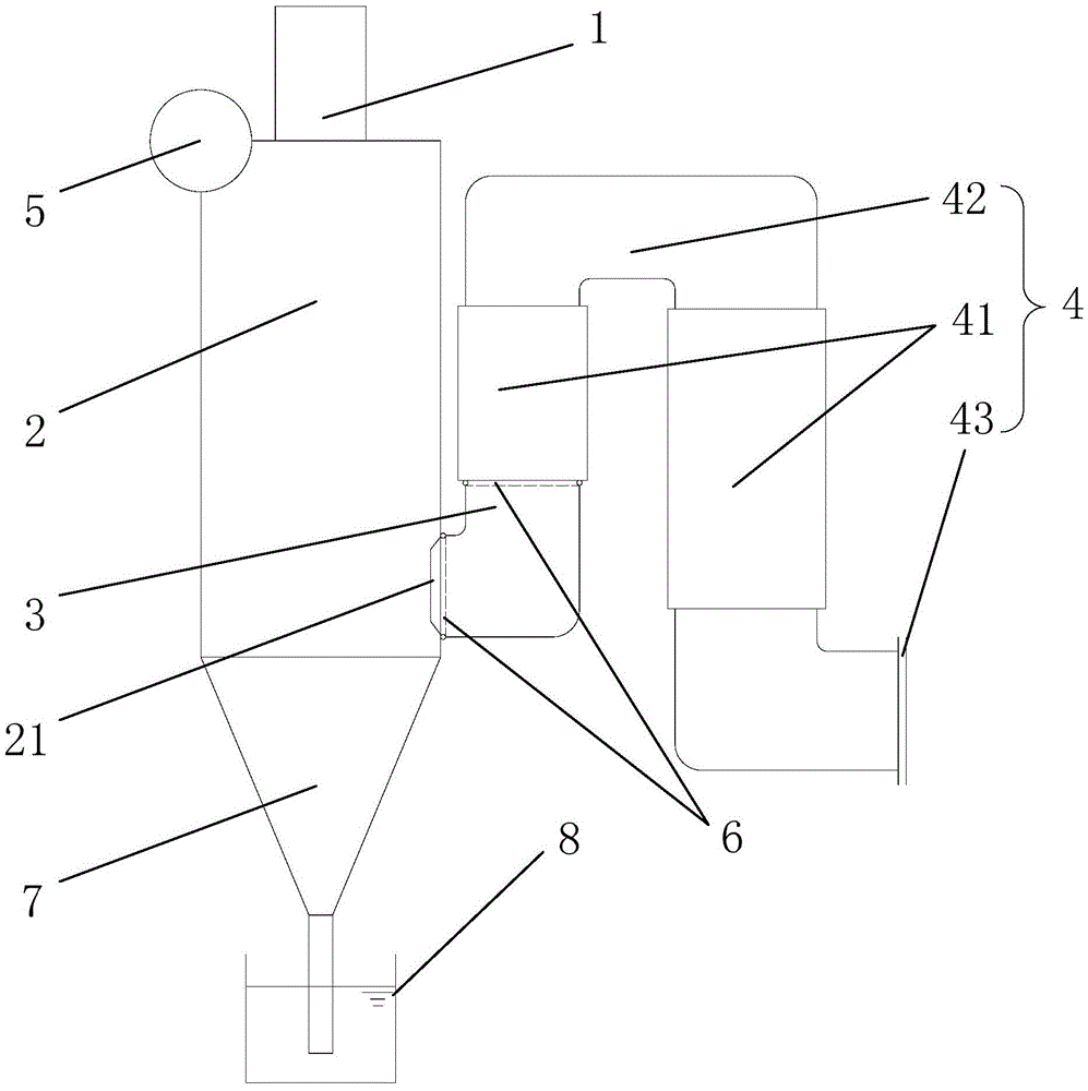
[0021] Such as figure 1 , figure 2 As shown, what this embodiment proposes is a vertical full-membrane wall water-fire tube boiler, which includes a burner 1, a vertical furnace 2 that adopts a full-membrane wall structure, and a vertical furnace 2 that adopts a full-membrane wall structure. The turning smoke chamber 3, a heat exchanger 4 and a steam drum 5. Among them, the burner 1 is fixedly connected to the top of the furnace 2, and an outlet chimney 21 is arranged on one side of the furnace 2, and one end of the turning smoke chamber 3 is connected to the outlet chimney 21, and the other end is connected to the heat exchanger 4. 3 and the outlet chimney 21, the connection of the heat exchanger 4 is respectively provided with an annular header 6. The membrane-type wall water-cooled tube of the turning smoke chamber 3 communicates with the shell of the heat exchanger 4 through the annular header 6 at the heat exchanger 4; the steam drum 5 communicates with the turning smo...

Embodiment 2

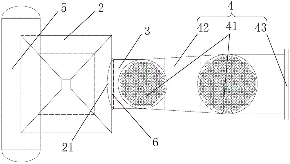
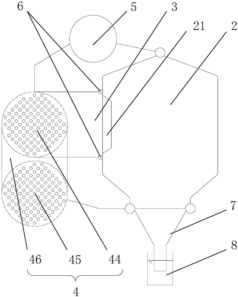
[0024] Such as Figure 3-6 As shown, what this embodiment proposes is a horizontal full-membrane wall water-fire tube boiler, which includes a burner 1, a horizontal furnace 2 with a full-membrane wall structure, and a full-membrane wall structure. The turning smoke chamber 3, a heat exchanger 4 and a steam drum 5. Among them, the burner 1 is fixedly connected to one end of the furnace 2, and an outlet chimney 21 is arranged on one side of the other end of the furnace 2, and one end of the turning smoke chamber 3 is connected to the outlet chimney 21, and the other end is connected to the heat exchanger 4. Annular headers 6 are respectively arranged at the joints of the turning smoke chamber 3 , the outlet smokestack 21 and the heat exchanger 4 . The membrane-type wall water-cooled tube of the turning smoke chamber 3 communicates with the shell of the heat exchanger 4 through the annular header 6 at the heat exchanger 4; the steam drum 5 communicates with the turning smoke ch...


PUM


Abstract

The invention relates to a full-film type wall water-fire tube boiler. The boiler comprises a hearth which is of a full-film type wall structure, a burner which is fixedly connected to one end of the hearth, a turning smoke chamber which is of a full-film type wall structure, a heat exchanger and a steam drum. An outlet smokestack is arranged on one side of the hearth. One end of the turning smoke chamber is connected with the outlet smokestack, and the other end of the turning smoke chamber is connected with the heat exchanger. The connecting joint between the turning smoke chamber and the outlet smokestack and the connecting joint between the turning smoke chamber and the heat exchanger are each provided with an annular header. A film type wall water-cooled tube of the turning smoke chamber communicates with a shell of the heat exchanger through the annular header located at the position of the heat exchanger. The steam drum communicates with the film type wall water-cooled tube of the turning smoke chamber through the annular header located at the position of the outlet smokestack. Meanwhile, the steam drum directly communicates with a film type wall water-cooled tube of the hearth and forms a circulation heat exchange channel. The full-film type wall water-fire tube boiler includes various structures, boiler capacity covers the full industrial boiler range, and thus the boiler can be widely applied to various conditions where water-fire tube boilers are needed.

Description

technical field [0001] The invention relates to a boiler, in particular to a full-membrane wall water-fire tube boiler. Background technique [0002] Membrane wall, also known as membrane water wall, refers to the furnace wall of a boiler welded into pieces by pipes and flat steel. The membrane wall has the advantages of simplicity, saving steel, good heat preservation and good air tightness, and it only needs to lay silicate heat preservation material outside the furnace, without building refractory bricks, so that the thickness and weight of the furnace wall are greatly reduced. Reduce and simplify the furnace wall structure and reduce the total weight of the boiler. At present, only water-tube boilers in the market generally have a full-membrane wall structure. Although coal-fired industrial boilers also use a membrane-type wall structure, they are mainly used in the furnace part, or the peripheral structure of the high-temperature convection tube bundle, and there are s...

Claims


Application Information

Patent Timeline
Patent Type & Authority Applications(China)
IPC IPC(8): F22B21/00F22B31/08F22B31/00
CPCF22B21/002F22B31/00F22B31/08
Inventor 王乃继肖翠微尚庆雨张鑫李小炯徐大宝纪任山李立新李婷梁兴程晓磊牛芳杨石刘振宇王永英
Owner CHINA COAL RES INST CCRI ENERGY SAVING TECH CO LTD
Why Eureka
Try Eureka