Grid-connected microgrid asymmetrical fault region detection device and diagnosis method

A technology of fault area and detection device, which is applied in the field of power grid system, can solve problems such as failure diagnosis of micro grid main network or contact area, and achieve the effect of meeting protection selectivity requirements, ensuring continuous power supply, and small power failure range

Inactive Publication Date: 2016-05-18
CHINA JILIANG UNIV
View PDF12 Cites 4 Cited by
  • Summary
  • Abstract
  • Description
  • Claims
  • Application Information

AI Technical Summary

Problems solved by technology

[0006] The purpose of the present invention is to overcome the deficiency in the prior art that the failure of the microgrid main network or contact area cannot be diagnosed, and to provide a networked microgrid asymmetrical fault area detection device that can accurately diagnose the location of the fault and diagnostic methods

Method used


Image

  • Grid-connected microgrid asymmetrical fault region detection device and diagnosis method
  • Grid-connected microgrid asymmetrical fault region detection device and diagnosis method
  • Grid-connected microgrid asymmetrical fault region detection device and diagnosis method

Examples


Embodiment 1

[0066] Such as figure 1 The illustrated embodiment is a detection device for an asymmetrical fault area of ​​a networked microgrid. The microgrid 1 is connected to the main grid 332 through the contact area 2, and the contact area includes the first circuit breakers CB connected in series. A , contact transformer 21 and the second circuit breaker CB B The fault detection device includes a first impedance measurement element 3 connected to the main grid side bus data, a second impedance measurement element 4 connected to the micro grid side bus data, an access switch 5 installed at the micro grid common connection point, and The negative-sequence voltage starting element 7 connected to the microgrid side bus bar data; also includes a microprocessor 6, an alarm 9 and a display 10, and the microprocessor is connected with the alarm, the display, the first impedance measuring element, and the second impedance measuring element respectively It is electrically connected with the ne...

Embodiment 2

[0081] Embodiment 2 includes all structures and steps of Embodiment 1, such as figure 1 As shown, embodiment 2 also includes a memory 8 and a voltage transformer 11, the negative sequence voltage starting element is electrically connected to the microgrid side bus through the voltage transformer, and both the memory and the voltage transformer are electrically connected to the microprocessor.

[0082] Step 100 in said embodiment 1 is replaced by the following steps:

[0083] (8-1) The microprocessor reads a certain phase voltage signal u(t) detected by the voltage transformer, sets the initial value of j to 1, and sets the initial value of i to 1; the fault threshold E is set in the memory ;

[0084] (8-2) Calculate the local maximum value of u(t) and obtain the upper envelope u through cubic spline interpolation up (t);

[0085] (8-3) Calculate the local minimum of the signal u(t) and obtain the lower envelope u through cubic spline interpolation low (t);

[0086] (8-4) ...

Embodiment 3

[0096] Embodiment 3 includes all structures and steps in Embodiment 1, and Embodiment 3 adopts the following steps to replace step 200 of Embodiment 1:

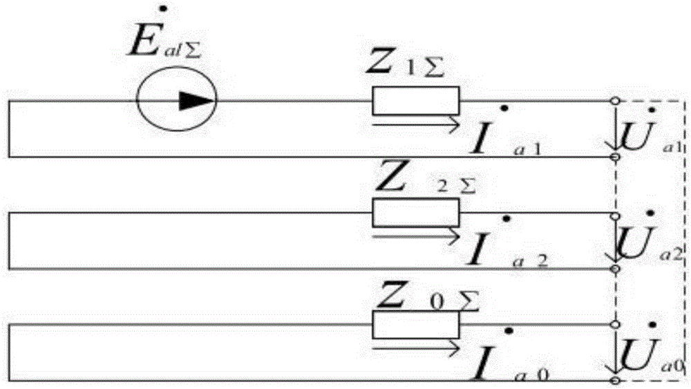
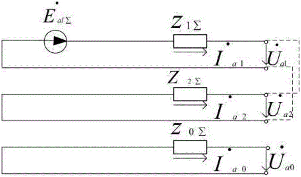
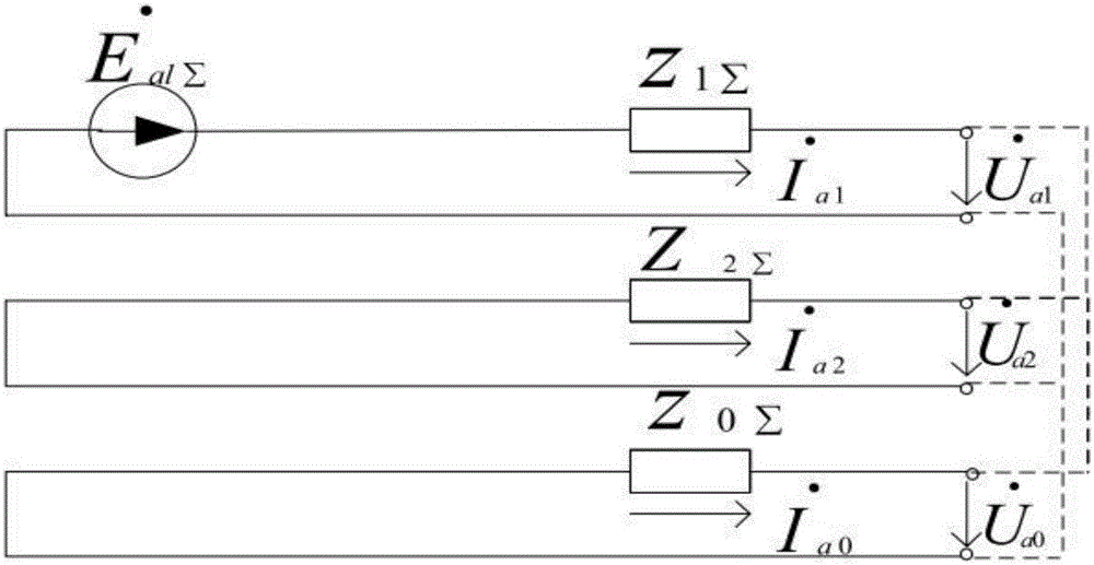
[0097] Step 210, calculate the real and imaginary parts of the impedance

[0098] The microprocessor reads the impedance value Z detected by the first impedance measuring element I and the impedance value Z detected by the second impedance element II ; set Z I The real part of Re(Z I ),Z II The imaginary part of is Im(Z I );

[0099] Step 220, using the rectangular coordinates of the impedance to judge the fault of the main network or the contact area

[0100] when and and and ,or and and and Then the microprocessor makes a judgment that there is a fault in the main network or the contact area, the display shows that there is a fault in the main network or the contact area, and the alarm sends out an alarm message; the microprocessor controls the access switch to disconnect, thereby connecting the micro ...


PUM


Abstract

The invention discloses a grid-connected microgrid asymmetrical fault region detection device and a diagnosis method. A microgrid is connected with a main grid through a contact region, the contact region comprises a first circuit breaker CBA, a contact transformer and a second circuit breaker CBB which are sequentially connected in series. The fault region detection device comprises a first impedance measuring element in data connection with a main grid side bus, a second impedance measuring element in data connection with a microgrid side bus, an access switch installed at a public connecting point of the microgrid, and a negative sequence voltage starting element in data connection with the microgrid side bus. The fault region detection device further comprises a microprocessor, an alarm and a display, wherein the microprocessor is electrically connected with the alarm, the display, the first impedance measuring element, the second impedance measuring element and the negative sequence voltage starting element. The grid-connected microgrid asymmetrical fault region detection device and the diagnosis method have the advantages of simple and fast diagnostic process, good reliability, high anti-interference capability and high operability.

Description

technical field [0001] The invention relates to the technical field of power grid systems, in particular to a networked micro-grid asymmetrical fault region detection device and a diagnosis method that can accurately diagnose the location of a fault. Background technique [0002] Due to the rapid development of electric energy and the needs of people's production and life, a new type of distributed power generation technology is also developing rapidly. Distributed power generation can make full use of the energy around it, and does not require large sites, small investment, and flexible power supply. However, due to the wide distribution range, a new type of microgrid needs to be established to solve its distribution problem. A micro-grid is a micro-grid composed of micro-power sources, loads, energy storage systems and control systems, which can be connected to the grid or run in isolation. The microgrid can not only complement the large power grid, optimize the allocatio...

Claims


Application Information

Patent Timeline
IPC IPC(8): G01R31/08
Inventor 王颖潘明九孙黎滢周敬尧蔡慧陈卫民
Owner CHINA JILIANG UNIV
Why Eureka
Try Eureka