Lyot filter based on circular polarizers
A filter and circular polarizer technology, which is applied in the field of optical signal processing and optical fiber sensing, can solve the problems of complex process, easy to be affected by the environment, etc., and achieve the effect of small environmental impact
- Summary
- Abstract
- Description
- Claims
- Application Information
AI Technical Summary
Problems solved by technology
Method used
Image
Examples
Embodiment 1
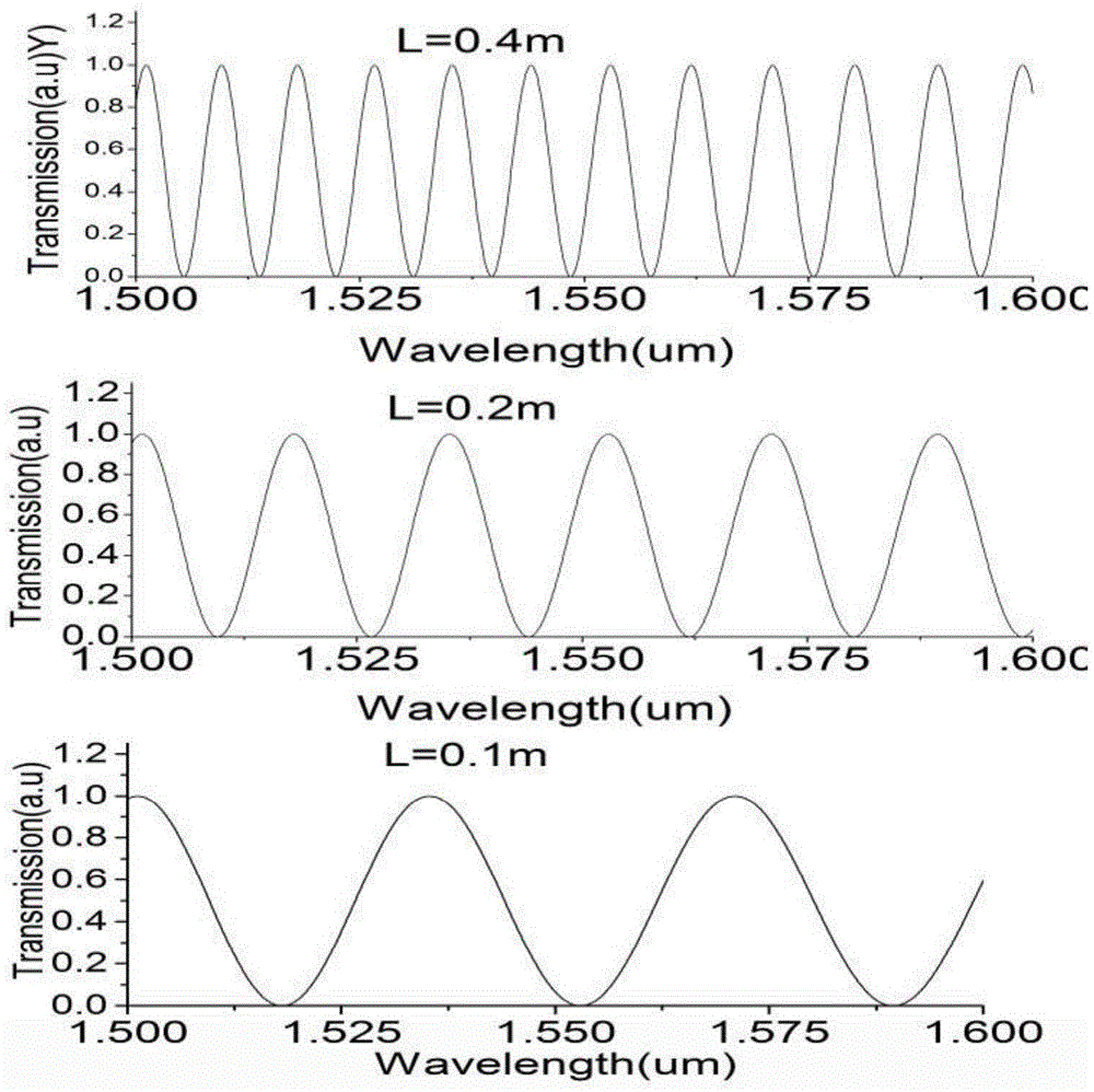
[0021] Two fiber-optic circular polarizers with a working wavelength range of 1500-1600nm, such as chiral fiber grating (Chiral FiberGrating), etc., and the optical fiber between the two circular polarizers (Circular Polarizer) is a birefringent fiber, such as polarization maintaining fiber (PMFiber), The length is L meters, and the refractive index of the slow axis is n 1 , the fast axis refractive index n 2 , the refractive index difference is Δn, which constitutes a Lyot filter. figure 1 A schematic diagram of the structure is given. figure 2 gives Δn=6.7552×10 -4 The normalized transmission spectrum shape of Lyot filter under different length L.
Embodiment 2
[0023] This example is a two-stage cascaded Lyot filter, sharing 3 circular polarizers, and the i-th circular polarizer is CP i (i=1,2,3), CP i with CP i+1 Between them is a polarization maintaining fiber, denoted as PMFiber i , with length L i . The length of each segment of PM fiber satisfies, L 1 = 2L 2 . Fig. 3 gives a schematic diagram of the structure. Fig.4 gives the L 1 =0.4m,L 2 =0.2m, the output normalized spectrogram.
Embodiment 3
[0025] This example is a three-stage cascaded Lyot filter, sharing 4 circular polarizers, and the i-th circular polarizer is CP i (i=1,2,3), CP i with CP i+1 Between them is a polarization maintaining fiber, denoted as PMFiber i , with length L i . The length of each segment of PM fiber satisfies, L 1 = 2L 2 = 4L 3 , that is, the length of the cascaded polarization-maintaining fiber is 1:2:4:...:2i (i is the number of cascaded series), and the cascaded filter will have a larger sidelobe suppression ratio at this time. Figure 5 A schematic diagram of the structure is given. Image 6 gives L 1 =0.4m, L 2 = 0.2m, L 3 =0.1m, the normalized spectrogram output.
PUM
 Abstract
Description
Claims
Application Information
 - R&D
- Intellectual Property
- Life Sciences
- Materials
- Tech Scout
- Unparalleled Data Quality
- Higher Quality Content
- 60% Fewer Hallucinations
Browse by: Latest US Patents, China's latest patents, Technical Efficacy Thesaurus, Application Domain, Technology Topic, Popular Technical Reports.
© 2025 PatSnap. All rights reserved.Legal|Privacy policy|Modern Slavery Act Transparency Statement|Sitemap|About US| Contact US: help@patsnap.com


