Light valve element and control method thereof and display device

A display device and component technology, applied in optics, static indicators, nonlinear optics, etc., can solve the problems of high technical difficulty, high cost, poor display effect, etc., and achieve the effect of simple working principle, easy preparation, and convenient control

Inactive Publication Date: 2016-05-18
BOE TECH GRP CO LTD +1
View PDF4 Cites 19 Cited by
  • Summary
  • Abstract
  • Description
  • Claims
  • Application Information

AI Technical Summary

Problems solved by technology

[0004] The light transmitted by the transmissive LCD device only accounts for a small proportion of the light emitted by the backlight source, and the power consumption is high; the reflective LCD device must rely on external light sources, so it cannot display images in dark environments, and the application scenarios are very difficult. Restricted; although transflective liquid crystal display devices are used in a wide range of scenarios, the display effect is poor. In a bright environment, only the reflective area works, and the transmissive area will be idle; in a dark environment, only the transmissive area works, and the reflective area is idle.
As a result, the transflective liquid crystal display device cannot maximize the use of external light sources or backlight sources; as for the MEMS switch device, its technical difficulty is relatively large, the manufacturing process is complicated, and the cost is relatively high.

Method used


Image

  • Light valve element and control method thereof and display device
  • Light valve element and control method thereof and display device
  • Light valve element and control method thereof and display device

Examples


Embodiment 1

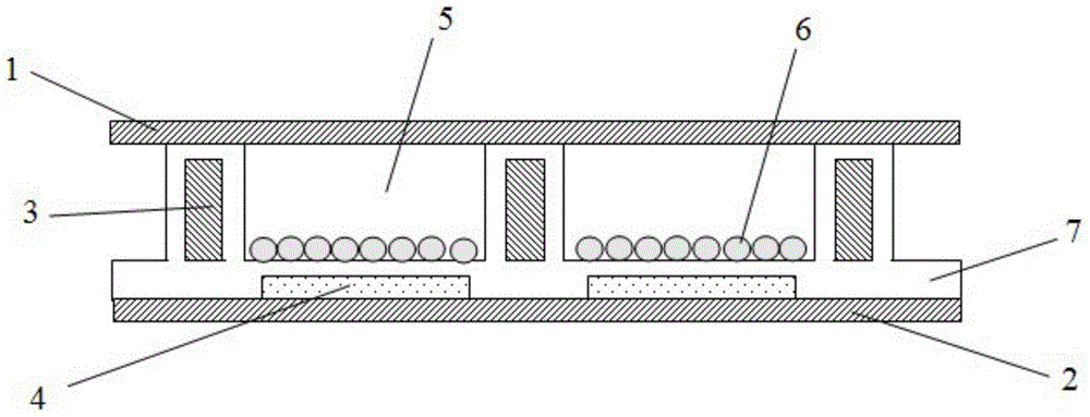
[0036] This embodiment provides a light valve element, the light valve element uses the principle of electrophoresis, by controlling the polarity of the charge on the first electrode and the second electrode, thereby controlling the position of the charged reflective particles, so as to realize the transmission of light and reflection.

[0037] The light valve element of this embodiment includes a first substrate and a second substrate facing in parallel, and a plurality of chambers are divided between the first substrate and the second substrate, and a first electrode and a second electrode are arranged in each chamber. Electrodes, the first electrode and the second electrode are insulated from each other and vertically arranged; each chamber is filled with electrophoresis buffer, and the electrophoresis buffer contains charged reflective particles, which can be adsorbed on the surface of the first electrode or the second electrode s surface.

[0038] figure 1 It is a struc...

Embodiment 2

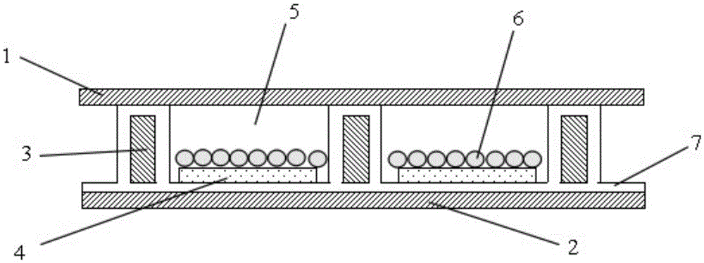
[0059] This embodiment provides a light valve element, which has a structure similar to that of the light valve element in Embodiment 1. The difference between it and Embodiment 1 is that, in the light valve element of this embodiment, the second electrode is arranged at the The top wall is a side close to the first substrate and parallel to the first substrate.

[0060] Figure 6 It is a structural schematic diagram of the light valve element of this embodiment, as Figure 6 As shown, the second electrode 4 is arranged on the top wall of the chamber, that is, on the side close to the first substrate 1, and parallel to the first substrate 1, the insulating layer 7 is arranged on the side wall and the bottom wall of the chamber, and the first electrode 3 It is arranged inside the insulating layer 7 , so that the insulating layer 7 plays the role of isolating the first electrode 3 and the second electrode 4 .

[0061] Other structures of the light valve element in this embodim...

Embodiment 3

[0064] This embodiment provides a control method of a light valve element, the control method is the control method of the light valve element in embodiment 1 or embodiment 2, comprising the following steps:

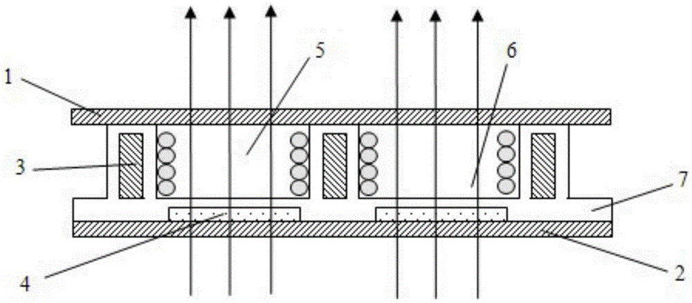
[0065] Controlling the first electrode to have a voltage of the same polarity as the charge of the reflective particles, and controlling the second electrode to have a voltage of the opposite polarity to the charge of the reflective particles, so as to realize the reflection of light;

[0066] The first electrode is controlled to have a voltage of the opposite polarity to the charge of the reflective particles, and the second electrode is controlled to have a voltage of the same polarity as the charge of the reflective particles, so as to realize the transmission of light.

[0067] The charges carried by the reflective particles can be either positive or negative. The control method of the light valve element in this embodiment can flexibly switch the light valve element...


PUM


Abstract

The invention provides a light valve element and a control method thereof and a display device, and belongs to the technical field of display. The problems that an existing light valve element is complex in structure, difficult to prepare, large in power consumption and high in cost can be solved. The light valve element comprises a first substrate and a second substrate which are oppositely arranged in parallel, the space between the first substrate and the second substrate are divided into multiple chambers, and first electrodes and second electrodes are arranged in each chamber, are insulated from each other and are perpendicular to each other; each chamber is filled with an electrophoretic buffer solution containing charged reflection particles, and the reflection particles can be adsorbed to the surfaces of the first electrodes or the surfaces of the second electrodes. The light valve element is simple in working principle, easy to prepare, little in power consumption, low in cost and convenient and efficient to control.

Description

technical field [0001] The invention belongs to the field of display technology, and in particular relates to a light valve element, a control method thereof, and a display device. Background technique [0002] Existing liquid crystal display devices are classified into transmission type, reflection type and transflective type according to different light sources used. Among them, the transmissive liquid crystal display device uses the backlight as the light source, and can display bright images in a dark environment; the reflective liquid crystal display device uses the front light source or the ambient light source as the light source, and the array substrate is made of metal or other materials with good reflection characteristics. The material layer of the transflective liquid crystal display device can be regarded as a transmissive liquid crystal display device and a reflective liquid crystal display device. In the combination of devices, a reflective area and a transmi...

Claims


Application Information

Patent Timeline
Patent Type & Authority Applications(China)
IPC IPC(8): G02F1/1335G02F1/133G02F1/167
CPCG02F1/133555G02F1/13306G02F1/167G02F1/1676
Inventor 杨慧光莫再隆周刚贺伟
Owner BOE TECH GRP CO LTD
Why Eureka
Try Eureka