Multistage serial-parallel conversion circuit

A technology for converting circuits and circuits, which is applied in the direction of logic circuit connection/interface layout, logic circuit coupling/interface using field effect transistors, etc., which can solve the problem of large number of logic, large power consumption of shift register structure, and limitation of maximum operating speed, etc. problem, to achieve the effect of logic reduction, reduction of the number of triggers, and increase of reliability

Active Publication Date: 2016-05-18
CAPITAL MICROELECTRONICS
View PDF3 Cites 4 Cited by
  • Summary
  • Abstract
  • Description
  • Claims
  • Application Information

AI Technical Summary

Problems solved by technology

Although the direct shift type serial-to-parallel converter can convert the 1-bit data signal input in series into the 10-bit data signal output in parallel, however, the number of bits of the flip-flop operating at a high-speed freque

Method used


Image

  • Multistage serial-parallel conversion circuit
  • Multistage serial-parallel conversion circuit
  • Multistage serial-parallel conversion circuit

Examples


Embodiment Construction

[0034] The technical solutions of the present invention will be described in further detail below with reference to the accompanying drawings and embodiments.

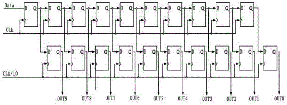
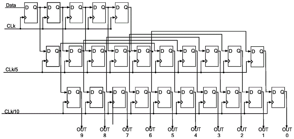
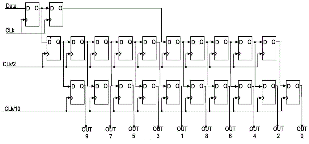
[0035] figure 2 It is a circuit diagram of a multi-stage serial-to-parallel converter in Embodiment 1 of the present invention, and the multi-stage serial-to-parallel converter circuit can be applied in a serializer / parallelizer interface.

[0036] Such as figure 2 As shown, the circuit of the multi-stage serial-to-parallel converter includes: at least three-stage D flip-flop groups;

[0037] The first-level D flip-flop group includes n cascaded D flip-flops (in this embodiment, 5 cascaded D flip-flops are taken as an example, that is, n=5), and the n cascaded D flip-flops have the same first clock signal CLK 1 , when the first clock signal CLK 1 When arriving, trigger all D flip-flops of the first-level D flip-flop group; The second-level D flip-flop group includes n×m cascaded D flip-flops (in this embodiment, ...


PUM


Abstract

The invention discloses a multistage serial-parallel conversion circuit, which is characterized by comprising at least three stages of D trigger groups. The first stage of D trigger groups comprises n cascaded D triggers with the same first clock signals; the second stage of D trigger groups comprises n*m cascaded D triggers with the same second clock signals; the third stage of D trigger groups comprises n*m cascaded D triggers with the same third clock signals; in the first stage of D trigger groups, the output end of the ath D trigger is connected with the input end of the ath D trigger in the second stage of D trigger groups; the output end of the ((m-1)*n+a)th D trigger in the second stage of D trigger groups is connected with the input end of the (m*n+a)th D trigger in the second stage of D trigger groups and is also connected with the input end of the ((m-1)*n+a)th D trigger in the third stage of D trigger groups; and n, m and a are all natural numbers, and a</=n.

Description

technical field [0001] The invention relates to the field of digital communication, in particular to a multistage serial-to-parallel conversion circuit applied in serializer / parallelizer interface. Background technique [0002] The invention relates to the field of electronic communication, and relates to a serializer / parallelizer (SERializer / DESerializer, SerDes). SerDes is an asynchronous data signal clock capture technology for all-digital circuit design, which is designed and implemented based on FPGA. A standard SerDes interface mainly includes the following modules: 8b / 10b encoder, 8b / 10b decoder, comma detector, parallel-to-serial converter, serial-to-parallel converter, clock and data signal recovery (Clock and Data Recovery, CDR), digital lock Phase loop (PhaseLockedLoop, PLL) and so on. Among them, the parallel-to-serial converter and the serial-to-parallel converter are important modules designed by Serdes. They work the fastest in the entire circuit and directl...

Claims


Application Information

Patent Timeline
IPC IPC(8): H03K19/0185
Inventor 易晶晶邵屹峰王岳刘明
Owner CAPITAL MICROELECTRONICS
Why Eureka
Try Eureka