Automatic stud welding device applicable to T-shape welding studs

An automatic welding and stud welding technology, applied in welding equipment, welding accessories, arc welding equipment, etc., can solve the problems of operator safety hazards, low yield, low productivity, etc., and achieve stable welding quality, safe use, and installation. and easy maintenance

Active Publication Date: 2016-05-25
胡长建
View PDF6 Cites 6 Cited by
  • Summary
  • Abstract
  • Description
  • Claims
  • Application Information

AI Technical Summary

Problems solved by technology

[0003] Since there is no automatic feeding technology for T-shaped welding studs with ceramic rings and no automatic welding torch that can automatically clamp and disengage T-shaped welding studs and ceramic rings, so that the current arc studs for T-shaped welding studs Welding is mainly manual operation, not

Method used


Image

  • Automatic stud welding device applicable to T-shape welding studs
  • Automatic stud welding device applicable to T-shape welding studs
  • Automatic stud welding device applicable to T-shape welding studs

Examples


Example Embodiment

[0035] Example

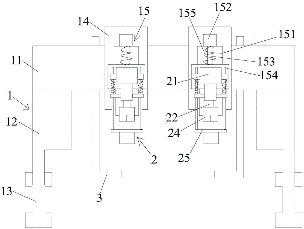
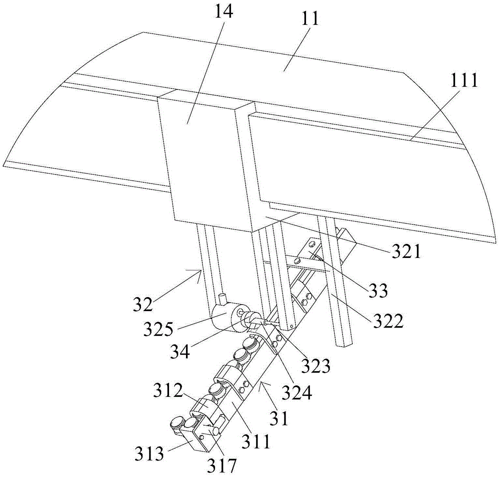
[0036] combine figure 1 and figure 2As shown: a device suitable for automatic stud welding of T-shaped welding studs provided by the present invention includes a three-axis motion platform 1, several automatic welding guns 2 and several automatic feeding mechanisms 4, and each automatic welding gun 2 is equipped with an automatic feeding mechanism 4. The three-axis motion platform 1 includes a crossbeam 11, legs 12, ground rails 13, a horizontal motion slider 14 and a three-axis motion drive mechanism (not shown in the figure), and the crossbeam 11 is fixed on the legs 12 , the legs 12 are slidably connected to the corresponding ground rail 13, the horizontal movement slider 14 is slidably connected to the slide rail 111 provided on the beam 11, and a lifting movement mechanism 15 is fixed on the horizontal movement slider 14, The lifting motion mechanism 15 includes a fixed base A151, a lifting motor 152, a lifting shaft 153 and a mounting base 154. A spr...


PUM


Abstract

The invention discloses an automatic stud welding device applicable to T-shape welding studs. The automatic stud welding device comprises a three-axis movement platform, a plurality of automatic welding guns and a plurality of automatic feeding mechanisms, wherein the three-axis movement platform comprises a crossbeam, support legs, ground rails, horizontal movement sliding blocks and a three-axis movement driving mechanism, and lifting movement mechanisms are fixed on the horizontal movement sliding blocks; the automatic welding guns comprise welding shells, main shaft bodies, main shaft body driving mechanisms, welding stud chucks and ceramic ring clamps, and the welding gun shells are fixedly connected with the lifting movement mechanisms; the automatic feeding mechanisms comprise feed collets and mounting brackets, the feed collets are obliquely mounted on the mounting brackets and can move left and right or front and back, and the mounting brackets are fixedly connected with the horizontal movement sliding blocks at the corresponding positions. According to the automatic stud welding device, the automatic conveying of the T-shape welding studs sleeved by ceramic rings and the automatic clamping and separating of the T-shape welding studs and the protecting ceramic rings are realized; by combining the automatic stud welding device with the three-axis movement platform, the automatic stud welding of the T-shape welding studs can be realized.

Description

technical field [0001] The invention relates to a stud welding device, in particular to a device suitable for automatic stud welding of T-shaped welding studs, belonging to the technical field of stud welding equipment. Background technique [0002] T-shaped welding studs (also known as cylindrical head welding studs) are widely used as shear connectors (also known as shear keys) in steel structures and "steel-concrete" structures in construction and bridge construction. The stud welding method is planted and welded on steel beams, steel columns and other structures. A project (a high-rise building or a bridge) requires tens of thousands or even hundreds of thousands of T-shaped welding studs. According to statistics, the annual welding volume of T-shaped welding studs in Japan is 60 million, while the annual demand for T-shaped welding studs in steel structure buildings in my country is tens of millions. During the welding process, it is necessary to use a ceramic ring to...

Claims


Application Information

Patent Timeline
IPC IPC(8): B23K9/20B23K9/32
CPCB23K9/206B23K9/32
Inventor 胡长建邓显红
Owner 胡长建
Why Eureka
Try Eureka