Device and method for making straight edge holes in outward-flanging mode

A technology of turning holes and straight edges, applied in the direction of manufacturing tools, other manufacturing equipment/tools, etc., can solve the problem of difficult to form hole structure and other problems, and achieve the effect of small axial size

Active Publication Date: 2016-05-25
INST OF METAL RESEARCH - CHINESE ACAD OF SCI
View PDF6 Cites 3 Cited by
  • Summary
  • Abstract
  • Description
  • Claims
  • Application Information

AI Technical Summary

Problems solved by technology

[0004] The purpose of the present invention is to overcome the deficiencies in the traditional technology, provide a device and method for making straight-sided holes outward, solve the problem that the previous technology is difficult to form the hole structure on the curved surface, and finally obtain the wall thickness Hole-boring parts with uniformity and high roundness precision

Method used


Image

  • Device and method for making straight edge holes in outward-flanging mode
  • Device and method for making straight edge holes in outward-flanging mode
  • Device and method for making straight edge holes in outward-flanging mode

Examples


Embodiment 1

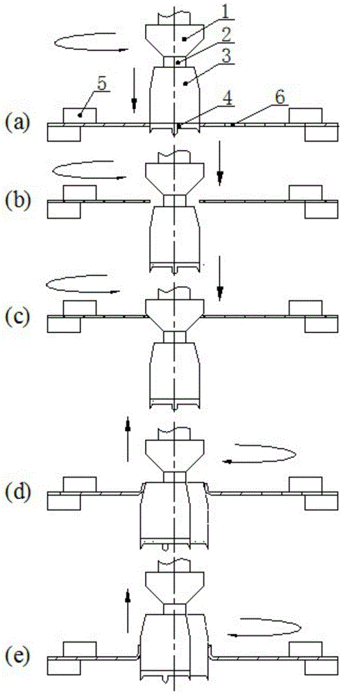
[0034] In this embodiment, the straight edge hole is turned outward on the flat blank, such as figure 1 As shown, the process of turning the hole using the above-mentioned straight edge outward turning tool includes the following steps:

[0035] 1) Choose a conical chamfering grinding wheel 1 with a suitable size, and fix it on the step of the rotating spindle 2 with screws;

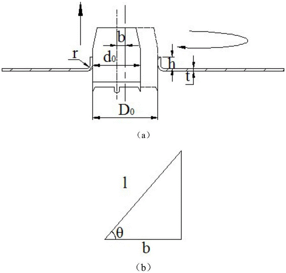
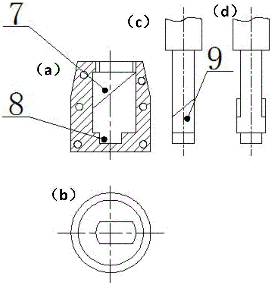
[0036] 2) According to the height of the turning hole and the wall thickness of the sample, determine the diameter of the turning hole eccentric wheel, the length of the vertical section (cylindrical section) and the length of the conical section, and the size of the cone angle, and make a turning hole eccentric wheel 3 of a corresponding size, and Match the internal inclined slideway of the eccentric wheel with the inclined slide block on the rotating main shaft, and fix them with screws to complete the assembly of the hole turning eccentric wheel;

[0037] 3) According to the diameter of the prefabric...

Embodiment 2

[0053] In this embodiment, the straight edge hole is turned outward on the blank of the space curved surface, and the schematic diagram of its structure and process flow is as follows Figure 4 shown.

[0054] The difference from Example 1 is:

[0055] Difference 1: The base of the deformation body is a curved pipe structure.

[0056] Difference 2: It is relatively difficult to process prefabricated holes and locate them on the blank whose deformation base surface is a curved surface.

[0057] Difference 3: During the hole turning process, the contact state between the blank hole wall and the hole turning device is different.

[0058] Difference 4: The contact state between the chamfering grinding wheel and the edge of the prefabricated hole of the curved surface blank is different.

[0059] Using the turning hole obtained in this embodiment, while ensuring the surface smoothness and dimensional accuracy of the inner wall of the turning hole, the rotational movement of the ...


PUM


Abstract

The invention discloses a device and method for making straight edge holes in an outward-flanging mode and belongs to the technical field of local formation of sheet materials or pipe fittings. The outward hole flanging device comprises a replaceable chamfering grinding wheel, a rotating spindle, a hole flanging eccentric wheel and an opening drill bit; the replaceable chamfering grinding wheel is fixed to the spindle, and the upper end of the rotating spindle is clamped to a chuck of a drilling machine or a numerically-controlled machine tool; the hole flanging eccentric wheel is fixed to the rotating spindle, relative movement and locking with the spindle is achieved through an internal inclined slideway and a bottom groove, the appearance of the component is divided into a conical segment and a cylindrical segment, and pre hole flanging and shaping are achieved through the matching function. Compared with the prior art, four processes of hole opening, chamfering, hole flanging and shaping are completed at a time, and overall machining efficiency is improved; hole flanging is achieved through eccentric rotating motion of an eccentric wheel, the spindle only needs to rotate and move up and down, and the motion difficulty of a hole flanging tool is remarkably lowered.

Description

technical field [0001] The invention relates to the technical field of partial forming of sheet metal or pipe fittings, in particular to a device and method for turning outward straight-side holes, which can realize prefabricated holes and straight-side outwardly turning holes of sheet metal or pipe parts at the same time. Background technique [0002] Turning straight-sided holes is a traditional sheet metal forming process, but the previous hole turning process has complex mold structure and large size, and it is difficult to turn outward holes on complex closed surface structures. In addition, there are prefabricated There are many problems such as the need to carry out the hole and the turning process separately. [0003] Chinese invention patent 200720090374.2 discloses a rotary tool for turning holes in T-shaped pipes, which has a simple structure and high production efficiency, and can turn metal pipe fittings that need to be turned outwards. However, the degree of a...

Claims


Application Information

Patent Timeline
Patent Type & Authority Applications(China)
IPC IPC(8): B23P23/04B21D19/08
CPCB21D19/088B23P23/04
Inventor 徐勇陈大勇张士宏马彦
Owner INST OF METAL RESEARCH - CHINESE ACAD OF SCI
Why Eureka
Try Eureka