

Centering type locking mechanism based on piezoelectric motor drive
A piezoelectric motor and locking mechanism technology, applied in the direction of generator/motor, piezoelectric effect/electrostrictive or magnetostrictive motor, positioning device, etc., can solve the problems of complex structure, electromagnetic interference, etc. Simplified assembly process, no electromagnetic interference, and improved reliability
- Summary
- Abstract
- Description
- Claims
- Application Information
AI Technical Summary
Problems solved by technology
Method used
Image

Examples
specific Embodiment approach 1
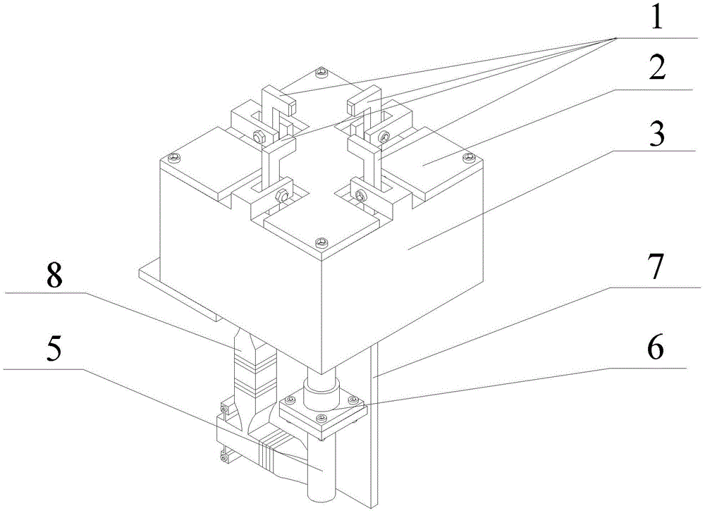
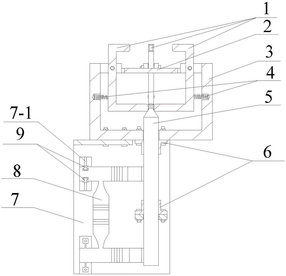
[0030] Specific implementation mode one: refer to Figure 1 to Figure 3 Describe this embodiment in detail. The centering locking mechanism driven by a piezoelectric motor described in this embodiment includes four jaws 1, a limit plate 2, a clamp body 3, four springs 4, and a wedge drive. Shaft 5, two shaft outlet sleeves 6, motor fixing plate 7 and piezoelectric motor 8,
[0031] The clamp body 3 is a cube structure with an upper end opening, and a U-shaped groove is respectively arranged in the top middle of the four side walls of the clamp body 3, and a jaw 1 is arranged in each U-shaped groove along the up and down direction, and the U-shaped groove and the clamp The jaws 1 are hinged by bolts, and the bottom ends of the four jaws 1 are fixed together;
[0032] The lower end of each jaw 1 is connected with one end of a spring 4; the other end of each spring 4 is connected with the hole on the side wall of the clamp body 3 respectively,
[0033] The limit plate 2 is fixe...
specific Embodiment approach 2
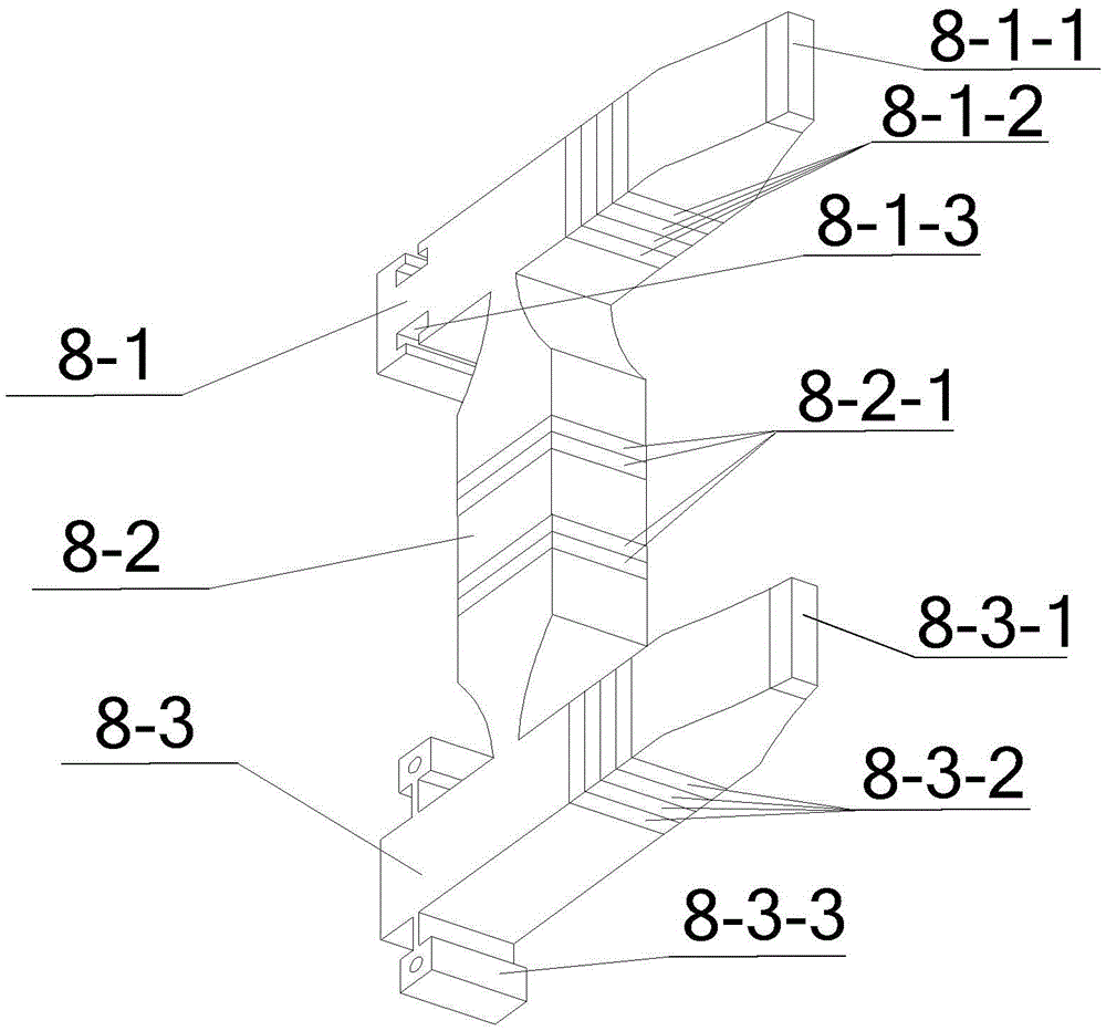
[0042] Specific embodiment two: This embodiment is to further explain the centering locking mechanism driven by a piezoelectric motor described in specific embodiment one. In this embodiment, the upper side transducer 8-1, the lower side transducer Both the transducer 8-3 and the vertical transducer 8-2 are composites composed of a metal body and piezoelectric ceramic sheets by pasting or clamping.
[0043] The upper side transducer 8-1 is symmetrically provided with slider fixing grooves 8-1-3 along the two sides of the vertical transducer 8-2 in the length direction, and each slider fixing groove 8-1-3 is embedded with A slide block 9, the slide block 9 is fixedly connected with the motor fixing plate 7,
[0044] The lower side transducer 8-3 is symmetrically provided with mounting bases 8-3-3 along the two sides of the vertical transducer 8-2 in the length direction,
[0045] The lower side transducer 8-3 is connected with the motor fixing plate 7 through the mounting base...
specific Embodiment approach 3
[0048] Embodiment 3: This embodiment is to further explain the centering locking mechanism driven by a piezoelectric motor described in Embodiment 1. In this embodiment, the drive shaft on the wedge drive shaft 5 is a hollow shaft , The wedge head and the drive shaft are connected by threads.
[0049] In this embodiment, the driving shaft is designed as a hollow shaft to reduce the mass of the shaft. At the same time, the wedge head and the driving shaft are processed separately, and then connected with threads, so that the consumables are less and the processing is convenient.
PUM
 Abstract
Description
Claims
Application Information